background image

18

On-Line 

EXPRESS

Configuration Utility for Windows 3.x

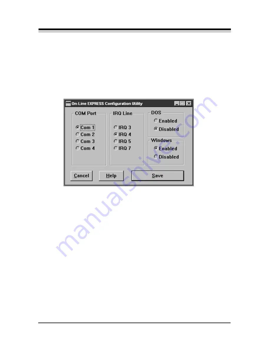
In the BocaModem Program Group, created during initial
driver installation, click on the “On-Line Express Setup
Utility”

. The following is displayed:

The options presented are the same as for the DOS version
as explained on the previous page with the exception of
“Automatic Settings”. For automatic setting, you must run
the DOS version of the Configuration Utility.

Summary of Contents for FDSP34AI

Page 1: ...1 V 34 PRODUCT CODE MV 34AI FDSP34AI...

Page 2: ...2 On Line EXPRESS...

Page 3: ...T you should check your DOS manual or seek assistance from you local computer dealer to install the product How to get Technical Assistance The dealer that you purchased this product or your computer...

Page 4: ...e entire package to your place of purchase so you may exchange it for a new one Your dealer should be able to provide you with an exchange far more quickly than by contacting us directly If for some r...

Page 5: ...al Support Fax 407 997 2163 Priority Service 900 555 4900 2 per minute Standard Free Technical Support 407 241 8088 Automated Fax Retrieval System 407 995 9456 On Line Support CompuServe GO BOCA Inter...

Page 6: ...tility for Windows 3 x 18 Step by Step Installation for Windows 95 19 Testing the Connection 25 I O Devices for the FDSP34AI 27 Section Two Product Overview 29 Section Three Troubleshooting 30 Appendi...

Page 7: ...as shown below If any items are missing or appear damaged contact your dealer for assistance CAUTION When working inside the computer always exit all applications and turn OFF power For additional saf...

Page 8: ...ndows 95 reports a problem with the modem port Remove diskette power back on and start Windows 95 Double click My Computer Control Panel Click Add New Hardware Click Next No Next Select Modem Next the...

Page 9: ...r OFF remove system cover choose an open ISA slot and gently insert the modem card YOU MUST INSTALL THE DRIVER DISKETTE SOFTWARE BEFORE INSTALLING THE MODEM 2 3 4 Connect supplied phone cable between...

Page 10: ...MIC Connecting Input Output Devices to the FDSP34AI LINE PHONE SPK MIC Connect microphone to the MIC connector MONO goes to SPK jack on modem STEREO goes to line in connector on a speaker Stereo Mono...

Page 11: ...rd make sure power is off Then turn your computer on If your system automatically starts in Windows exit to DOS 2 Insert the driver diskette and type A or B INSTALL and press ENTER An introductory scr...

Page 12: ...les normally C DOS 5 Next you need to specify whether or not Windows is installed on your machine and its location drive and directory Following that files are copied to C MODEM or another directory s...

Page 13: ...p 2 Should you need to change any settings later simply run the program OLESET as described on page 17 Now you are ready to physically install the modem in your computer Power down your system 10 Hand...

Page 14: ...dge until it snaps into place 13 Secure the modem into place by aligning its metal retaining bracket with the hole in the top edge of the system s rear panel Fasten the metal bracket with the screw re...

Page 15: ...he modem 2 If a phone is plugged into a wall jack unplug the phone cable Then plug the other end of the supplied modem cable into the telephone wall jack 3 To continue using the phone connect the phon...

Page 16: ...free more memory for other programs you are running Windows support is established by a series of drivers in your SYSTEM INI file The Configuration utility edits the SYSTEM INI file based on the sett...

Page 17: ...h Com Port Allows you to change the COM port settings must match jumper settings on board IRQ Allows you to change the IRQ settings must match jumper settings on board Automatic Settings Determines av...

Page 18: ...ial driver installation click on the On Line Express Setup Utility The following is displayed The options presented are the same as for the DOS version as explained on the previous page with the excep...

Page 19: ...rch for your new hardware Click Next and scroll to Ports Then click Next and Have Disk and specify A or B then OK 2 Click OK then Next again Windows 95 assigns an I O range and IRQ for the modem Note...

Page 20: ...gain Files are now copied into the WINDOWS SYSTEM subdirectory Click Finish NOTE If you view the Device Manager information before shutting down and installing the modem Windows 95 reports a problem w...

Page 21: ...s rear panel Fasten the metal bracket with the screw removed in step 5 8 Replace the system cover reconnect any detached devices and power cords remove diskette and power up your computer 9 After rebo...

Page 22: ...em from the models list Boca Research 28 8Kbps MV 34AI or Boca Research 28 8Kbps FDSP34AI speakerphone model 12 Then click Next then select the COM port that was installed in Step 1 13 Select Next Fin...

Page 23: ...ick Properties and select the Resources tab Click either Input Output Range or Interrupt Request then Change Setting Note carefully any resource conflicts in the lower box and choose a different setti...

Page 24: ...he modem The LINE jack is the topmost jack on the modem 3 If a phone is plugged into a wall jack unplug the phone cable Then plug the other end of the supplied modem cable into the telephone wall jack...

Page 25: ...diskettes and manual for installation instructions After installing and starting your communications software enter terminal mode IMPORTANT If you are not in terminal mode and you type AT commands at...

Page 26: ...on hook This confirms that the modem has been successfully installed into your computer Your modem is now ready for use Continue now with your communications software and documentation If you are conn...

Page 27: ...d board and for playback and call monitoring Attach the stereo end of the stereo mono cable to the line in connector on your sound card If your sound card does not have a line in connector you will ne...

Page 28: ...NO goes to SPK jack on modem Stereo Mono Audio cable NOT SUPPLIED STEREO goes to line in connector on a speaker Connect microphone NOT SUPPLIED to the MIC connector NOTE For information on microphone...

Page 29: ...erformance The modem supports the V 34 protocol as well as V 32bis which provides high speed data transmission with V 42bis MNP5 data compression and V 42 MNP2 4 error control In addition to fax and d...

Page 30: ...ftware installation Check the connections between the modem and the computer and the modem and the telephone line Make sure the telephone jack is operational as described above The telephone line may...

Page 31: ...ts Make sure the echo command is set to ON Change to echo with the ATE command Make sure the local yours and remote modem configurations are compatible Verify that both modems are operating with the s...

Page 32: ...hine Check for any loose connections Re try the connection by dialing the number several times You may be experiencing line interference An incoming call may have broken the connection if a call waiti...

Page 33: ...POSSIBLE REMEDY You receive the message Cannot Open Port Check your SYSTEM INI file and make sure that that the line COMM DRV COMM DRV is in the file If not edit the statement and restart Windows Trou...

Page 34: ...The microphone element must be of the electret type also known incorrectly as a condenser type The microphone in most telephone handsets is of this type The FDSP34AI was designed for a microphone sens...

Page 35: ...S V 32 9600 4800 CCITT ITU TSS V 22bis 2400 CCITT ITU TSS V 21 300 CCITT ITU TSS V 23 600 75 1200 75 Bell 212A 1200 Bell 103 300 Fax protocols CCITT ITU TSS V 17 14400 12000 9600 7200 CCITT ITU TSS V...

Page 36: ...an be configured as I O port address COM1 COM2 COM3 or COM4 and IRQ 3 4 5 or 7 The default setting for the modem is I O port address COM2 using IRQ3 NOTE The modem cannot share the same interrupt or C...

Page 37: ...etermined by turning the equipment off and on the user is encouraged to try to correct the interference by one or more of the following measures Re orient or relocate the receiving antennae Increase t...

Page 38: ...e customer s premises which remains connected to the telephone network shall occur by reason of such withdrawal Incidence of Harm Should terminal equipment or protective circuitry cause harm to the te...

Page 39: ...pany cause to request the user to disconnect the equipment Users should ensure for their own protection that the electrical ground connections of the power utility telephone lines and internal metalli...

Page 40: ...44 60 for additional details Hayes compatible commands consist of a basic command set and an extended command set The basic set involves functions such as dialing a number or putting the modem on hoo...

Page 41: ...een the rate at which data reaches a device and the rate at which the device processes and transmits AT E1 tells the modem to monitor line quality and request a retrain adjustment to the connection S...

Page 42: ...elephone line noise and other signal distortions There are several classes of MNP operation also referred to as service classes Class 5 maximizes data transfer rate and provides compression which can...

Page 43: ...ca V 24 CCITT serial interface standard EIA RS232 D V 32 CCITT standard for 9600bps and 4800bps communications V 32bis CCITT standard for an extensive range of high speed modems operating at 14 400bps...

Page 44: ...5bps answer mode receive 75bps transmit 1200bps ATB3 Selects V 23 originate mode receive 75bps transmit 1200bps answer mode receive 1200bps transmit 75bps ATB15 Selects V 21 when the modem is at 300bp...

Page 45: ...structs the modem to provide information about itself ATI0 Displays the product identification code ATI1 Displays the checksum ATI2 Displays ROM checksum as OK or ERROR ATI3 Same as I0 ATI4 Returns fi...

Page 46: ...he modems detects signal distortion or line noise ATO3 14 Forces the modem to a new rate as defined in S62 ATQ Results Code Display Option Controls whether or not result codes are displayed to your co...

Page 47: ...lays CONNECT or 1 for all speeds ATX1 Displays connect message according to ATW and AT V blind dial ignores busy tone ATX2 Displays connect message according to ATW and AT V waits for dial tone ignore...

Page 48: ...ier state of the remote modem is handled AT C0 State of carrier from remote modem is ignored AT C1 State of carrier from remote modem is tracked default AT D Data Terminal Ready Option Interprets how...

Page 49: ...using standard ASCII control characters to pause or resume data transmission RTS CTS pacing a hardware based method uses an electrical signal Signals are exchanged as follow RECEIVER TRANSMITTER CTS O...

Page 50: ...opback test AT T7 Executes the remote digital loopback test with a self test AT T8 Executes the remote analog loopback test with a self test AT V View current configuration and user profile Used to di...

Page 51: ...ing AT Z2 Stores a 36 digit dial string AT Z3 Stores a 36 digit dial string AT percent Commands AT A Set Autoreliable Fallback Character Allows you to specify the character that tells the modem to ret...

Page 52: ...data from the remote modem faster than it can be processed enabling port flow control allows the modem to handle the data efficiently AT G0 Disables port flow control AT J Constant DTE Speed Option AT...

Page 53: ...send break to the remote modem 2 3 Immediately send break to the remote modem 4 5 Send break to the remote modem in sequence with data In on line data mode with normal mode receive break signal from r...

Page 54: ...AT Q3 RTS CTS hardware flow control default AT T Set Inactivity Timer Allows the modem to disconnect if no data activity has occurred for the selected period of time AT T0 Disable inactivity timer AT...

Page 55: ...describes their functions These registers affect various operating characteristics and allow you to obtain information about the modem as well as test the modem Each register has a factory set value...

Page 56: ...ace character S6 2 255 seconds 2 Wait time for Blind Dialing S7 1 255 seconds 60 Wait for carrier after dial S8 0 255 seconds 2 Pause time for dial delay S9 1 255 seconds 6 10 Carrier detect S10 1 255...

Page 57: ...13 Attempt to connect at V 34 19200bps 14 Attempt to connect at V 34 21600bps 15 Attempt to connect at V 34 24000bps 16 Attempt to connect at V 34 26400bps 17 Attempt to connect at V 34 28800bps S40 B...

Page 58: ...l Option reflects the Kn value S53 0 4 ASCII 3 Operating Mode Nn 0 N0 is selected 1 N1 is selected 2 N2 is selected 3 N3 is selected 4 N4 is selected S54 Bit Mapped Bit Mapped Registers S59 0 1 ASCII...

Page 59: ...d line CONNECT 5 Modem established a connection 1200 at 1200 1200bps NO 6 Modem did not detect a dial tone within 5 DIALTONE seconds after going off hook BUSY 7 Modem detected a busy signal NO ANSWER...

Page 60: ...CT 24 Connection made at 7200 bps 7200 CONNECT 25 Connection made at 12000 bps 12000 CONNECT 55 Connection made at 21600 bps 21600 CONNECT 56 Connection made at 24000 bps 24000 CONNECT 57 Connection m...

Page 61: ...ks Automatic AT J0 Q3 Microsoft Fax Automatic No string needed Procom Plus Fax Boca Modem V 34 Fax Data AT F C1 D2 DATA Setting Initialization String WINDOWS 3 1 Procom Plus Boca Modem V 34 Fax Data A...

Page 62: ...e MV 34KI 2 5 AT F C1 D2 N3S95 1 M Compuserve Hayes ATS0 0Q0V1 C1 D2 M Prodigy Auto detect No string to change Dial Up Setting Initialization String Internet GNN Hayes Comp Error correcting AT F C1 D2...

Page 63: ...u may call our technical support staff for assistance If you haven t referred to the Troubleshooting section do so now NOTE CALLING TECHNICAL SUPPORT WITHOUT COMPLETE AND ACCURATE INFORMATION CONCERNI...

Page 64: ...arts are defective but will not replace such parts until specific written authorization is received from you The cost of parts and labor involved in making such repairs will be billed to you C O D 5 W...

Page 65: ...which require Limited Warranty service during the warranty period should be delivered to BRI at the address in the Appendix Servicing Your Boca Product with proof of purchase and the Return Merchandi...

Page 66: ...CANT DE L APPAREIL POUR VERIFIER OU CONFIRMER SI L UTILISATEUR PEUT Y INSTALLER LUI MEME DES CARTES PERIPHERIQUES 2 CAUTION ALWAYS DISCONNECT MODEM BOARD THE ONE WITH THE TELEPHONE PLUG JACK FROM THE...

Page 67: ...67...

Page 68: ...68 On Line EXPRESS Manual Part No 9484 Rev 2 0...

Reviews: