background image

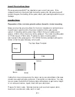
NOTE:  You may need to raise the motor to allow the gear rack to fasten 

properly to your gate bottom rail, so check this first by placing a piece of gear 

rack on top of the motors cog alongside the gate.  

Open/close the gate to ensure no fasteners are obstructing the rack.

There are 3 typical ways to fasten the motor to your concrete.

Option 1: If your gate is manufactured with 100 x 50mm rectangular bottom 

rail such as the BMGI low profile model and sits about 40mm off the ground 

with the wheels, you can bolt the motor directly to the concrete.

Hint: Option 2 and 3 are good for raising the motor to allow cables to be 

installed freely under the motor so you do not need to be too accurate with 

your cable location.

Option 2: If your gate is fitted with the standard wheel that raises the gate to 

approx. 50mm from the ground you can use high mounting blocks to lift the 

motor.  Position these spacers under the left and right sides of the motor and 

fasten to concrete.

Option 3: new concrete pad.  If your gate is above 50mm off the ground you 

can use the mounting plate supplied with the motor and the 4 threaded rods, 

1 in each corner to act as pylons.  The rods can be pressed into your concrete 

pad.  You can now line up the mounting plate.  Once the concrete pad has 

dried, you can now assemble, starting with the motor, washers and fasten 

together with 4 more nuts.

Installing the gear rack to the gate:

For your gate to function smoothly you will need to install the gear rack 

correctly.  The outcome is to have a 2mm gap between your 

gear wheel

 and 

the valley of the gear rack throughout the length of the gate.  Temporarily 

raise the motor by another 2mm using bolt-washer spacers under the motor 

mounting bolts. 

3/1

1

Summary of Contents for LW550

Page 1: ...Sliding Gate Operator User s Manual WARNING THIS PRODUCT MUST BE INSTALLED BY A QUALIFIED ELECTRICIAN...

Page 2: ...perating 2 Keep children away from the gate and the remote control 3 Do no adjust the setting of the control panel unless you understand what you are doing 4 Learn the use of the the emergency overrid...

Page 3: ...00mm from your wall post and approx 220mm in from the corner of the wall post The motor mounting plate is 170mm deep x 270mm wide Position the motor mounting plate side nearest to the gate approx 150...

Page 4: ...he standard wheel that raises the gate to approx 50mm from the ground you can use high mounting blocks to lift the motor Position these spacers under the left and right sides of the motor and fasten t...

Page 5: ...here wheels may be contacted as this will increase gate moving resistance dramatically We strongly recommend you leave your gear rack over hanging approx 100mm until after you have fitted your magnet...

Page 6: ...il you see L6 light up on the main control board then adjust magnet on bracket and secure To install HIGH magnet open gate full and pull back 50mm now slide the HIGH magnet bracket along the racking t...

Page 7: ...function Turn clockwise to increase force to desired setting TORQUE Adjust motor s power clockwise is bigger Have the gate in the closed position and lock in clutch give the gate a push to make sure...

Page 8: ...ng as this will erase wipe all remotes tuned Note only 30 remotes will tune into the on board receiver Erase all remotes Hold the Study button down for 5 seconds now all remotes will be erased Remote...

Page 9: ...s Using telecom wire Important Note Terminals for eye beams are found in the bottom left corner of the main control board To install IR beams you will need power to both IR beams Connect one IR beam t...

Page 10: ...functioning if fitted 3 Can t locate accurately Distance of the magnetic bracket Internal Magnet is damaged Adjust position of magnet bracket Change internal magnet 4 Clutch can t work Operating handl...

Page 11: ...ubstitute for a poorly functioning gate Warranty 1 12 months warranty from date of purchase warranty does not cover incorrect installation or damage by fusion and other insects 2 Warranty replacement...

Page 12: ...ch input terminal Closing direction Common terminal Limist switch input terminal Open direction 15V 100mA max Power output Common terminal Infrared safety electric eye Closing direction input terminal...

Reviews: