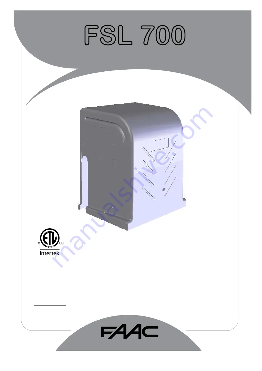
background image

Slide Gate Operator

FAAC International Inc.

Headquarter & East Coast Operations

3160 Murrell Rd

Rockledge, FL 32955

Tel. 800 221 8278

www.faacusa.com

FAAC International Inc.

West Coast Operations

357 South Acacia Avenue

Fullerton, CA 92831

FSL 700

UL325 - UL991

Summary of Contents for FSL700

Page 1: ...nternational Inc Headquarter East Coast Operations 3160 Murrell Rd Rockledge FL 32955 Tel 800 221 8278 www faacusa com FAAC International Inc West Coast Operations 357 South Acacia Avenue Fullerton CA...

Page 2: ......

Page 3: ...Power Guidelines 15 AC Power Connection 15 Battery Power Connection 16 Accessory Power 16 Master Slave Connection 17 Gate Operator Adjustments Reverse Sensitivity Adjustment 18 Reverse Sensitivity Sh...

Page 4: ...user is prevented from reaching over under around or through the gate to operate the controls Controls located outdoors or those that are easily acces sible shall have security features to prevent una...

Page 5: ...n therefore use caution when touching the external housing of the gate operator Use the manual release mechanism according to the procedures presented in this manual Before performing any cleaning or...

Page 6: ...es loading docks or other locations not intended to service the general public RESTRICTED ACCESS VEHICULAR GATE OPERATOR CLASS IV A vehicular gate operator system intended for use in guarded industria...

Page 7: ...gate to prevent the user from coming in contact with the gate while operating the controls All activating devices must be installed in a clear line of sight with the gate and its travel Be sure to mo...

Page 8: ...ntact sensors since some devices only cover a select area For example a photo beam will not cover the full height of a gate fence area Refer to the diagram below Vehicular Gate Only Pedestrian Access...

Page 9: ...ure such as a building wall or fence to reduce the risk of entrapment in this area Install over travel stops at both ends of the gate rail or track to help prevent the gate from derailing Be sure the...

Page 10: ...ditional front mount or the rear mount method Both methods have their advantages and will reliably open the gate The front mount method places the operator up front near the flow of traffic and uses a...

Page 11: ...cation of the operator can not be predetermined bring all conduits up to one side and terminate in a Bell Box Make connections to the operator using water tight flex conduit 6 Form the concrete pad as...

Page 12: ...each other Tighten the anchor bolts to securely hold the operator GATE GATE OPERATOR 3 5 CORRECT WRONG GATE Chain Connection Front Mount Once the gate operator is securely bolted down the chain may be...

Page 13: ...in from the lower chain idler is level with the bottom of the endless idler Approximately 11 Make sure the chain will be in a straight line and same height as the lower idler sprocket 5 Weld the botto...

Page 14: ...sary to fine tune the full open and full closed positions RIGHT LEFT Gate Operator Direction The gate operator uses a DIP switch setting to determine the open and close direction To set the Open Close...

Page 15: ...AC power should be supplied from a circuit breaker panel and must have its own dedicated circuit breaker This supply must include a green ground conductor 3 Only use U L approved 14 AWG or larger 600...

Page 16: ...is used frequently consider the current draw of the accessories The lower the current draw the longer the battery power supply will last Additional 24 VDC for accessories may be found on the Radio Te...

Page 17: ...pairs between the Master operator and the Slave operator Make the connections on the Master Slave Terminal Block following the schematic below Recommended Wire Outdoor Rated CAT 5 Cable If shielded m...

Page 18: ...ully cycles without stopping 8 Place an immobile object in the open path of the gate to stop the gate while in travel The gate should stop and enter a Soft Shutdown upon striking the object 9 Place an...

Page 19: ...op Switch to be used ON Allows a NC Stop Switch to be used Stop Switch must be installed for this setting to be ON 9 Battery Cycle OFF Cycles gate until batteries are too low and stops Switch 5 must b...

Page 20: ...Reverse Photo Open Photo Close GND GND Edge Open Edge Close 24V DC Open 2 Open 1 Reverse 2 Reverse 1 Shadow 2 Shadow 1 Maglock Mon Light Master Slave Interconnect External Loop Detectors Light Com Li...

Page 21: ...ut The Input is only active during close cycle 1 An input during the close cycle will stop the gate and reverse it to the full open position If the Close Timer option is ON it will be restarted when t...

Page 22: ...opped position until a renewed intended activation input is received open close fire access radio If the close timer option is ON it will be disabled until a full cycle com pletes Edge Open safety Inp...

Page 23: ...verse Photo Open Photo Close GND GND Edge Open Edge Close 24V DC Fire Access Reset GND GND Stop Close Open OPEN CLOSE STOP Fire Access Reset GND GND Stop Close Open RESET Standard Reverse Connection T...

Page 24: ...n an Access Device is active the Access LED will light Fire Access Reset GND GND Stop Close Open TELEPHONE ENTRY DIGITAL LOCK CARD READER Fire Lock Connection Fire Lock Controls such as Knox Locks and...

Page 25: ...NO con tact Power must be applied externally Connecting Solenoid Maglocks 1 Set Master and Slave DIP Switch 10 to ON 2 Connect Solenoids to the external power supply and Solenoid Com and N C outputs f...

Page 26: ...stalled to help keep the batteries charged NOTE Solar and battery backup power are for limited operations and not intended for high traffic applications Fully charged batteries can operate a gate from...

Page 27: ...of the driveway and into rigid conduit under ground Seal this joint to protect the wires Press the loop wire to the bottom of the loop slot Use Backer Rod foam rubber to protect and keep the loop wire...

Page 28: ...onnect Reverse Loops wires to REVERSE 1 and 2 For fail safe operation connect reverse loops in series 2 Connect Open Loop wires to OPEN 1 and OPEN 2 Shadow Reverse Open R EVERSE L OOP R EVERSE L OOP O...

Page 29: ...ove the motor from the gearbox Both sensor lights should be on Pass a flat screw driver between Sensor 1 and Sensor 2 on the motor plate The Sen sor LED on the control board should turn off and on as...

Page 30: ...at sink and faceplate assembly UL2016 2 GC 2002 Faceplate GC 2003 Faceplate UL2016 3 GC3000 Controller Assembly No PCB faceplate 4 MOTOR 0500 24 Motor 500W 24VDC 5 SL 0020 Gearbox 15 1 6 SL 1000 Limit...

Page 31: ...31 Part Part Number Description 10 SL 0010 Limit nut 11 SWITCH 0100 Limit switch 12 AAA 0450 Sensor cup assembly 13 WIRE 1101SK Sensors wire assembly with screws 14 AAA 0402 Motor Adapter Plate...

Page 32: ...ubject to misuse negligence or accident or has not been operated in accordance with FAAC International Inc s or FAAC S p A s instructions or has been operated under conditions more severe than or othe...

Reviews: