11
AQT-RCS
Instruction Manual
Adding a PCM
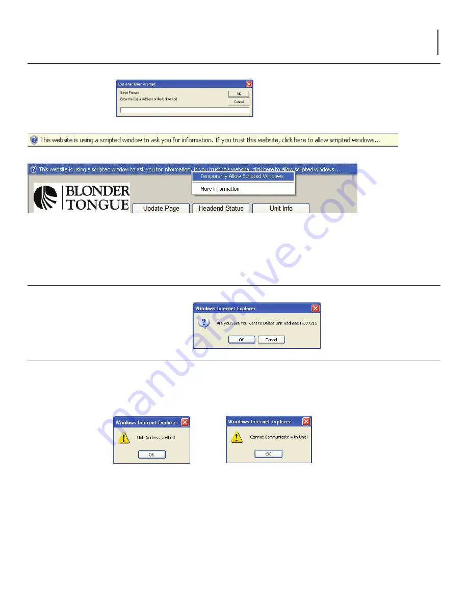
1. Click
Add AQT-PCM
to display the script dialog box.
2. Enter the digital address of each PCM unit to be installed in the AQT-RCS for the respective location.
The AQT digital address can be displayed by accessing the Interactive menu using the UP/DN arrow navigation keys on the
front panel LCD menu of each PCM unit.
Best results are achieved by entering the PCM addresses in the top to bottom order they are physically installed in the rack.
3. Click OK to Enter the PCM digital Address.
NOTE:
The
AQT-RCS
uses Javascript for the 'Add Unit' dialog box to pop up, this may need to be enabled in your browser.
Click anywhere on the warning bar (as pictured above & below) then select the Allow Scripted Windows option.
Deleting a PCM
1. Click
Delete Unit
to remove a PCM address from the installed list.
The confirmation dialog box will appear.
2. Click
OK
to remove the PCM address.
Checking a PCM address and communication
The AQT-RCS has an innovative tool built in to test the communication to a PCM address entered in the list.
This is extremely
valuable to ensure that the correct entry was made and that the wiring to the unit is correct.
Any unit installed can be
checked at anytime or sequence in the process and it does not matter where the unit physically resides in the headend chain.
1. Highlight a AQT address in the list by clicking on it.
2. Click
Check Unit
to query the digital address highlighted.
The AQT-RCS will attempt to communicate with the highlighted unit and report back a verification for successful communication
or a cannot communicate message if the attempt failed. This is a very valuable tool to ensure that all units entered are correctly
connected and the digital address matches the on-screen entry.
If the 'Cannot Communicate with Unit' error message is displayed:
1. Verify the AQT-PCM address is entered in the list correctly - the AQT-PCM digital address can be displayed by accessing the
interactive menu using the UP/DN arrow navigation keys on the front panel LCD menu of each PCM unit.
2. Check the cabling on the rear of the AQT-RCS and respective AQT-PCM
Ensure a standard 4-pin cross phone cable (RJ-11) is used from AQT-RCS to the RJ-11 IN port of the first AQT and a straight thru
RJ-11 jumper is used from the OUT port to the IN port of each subsequent AQT unit. (See Appendix A for Cable Details)


