background image

Maintenance

20

Cleaning and Preventive Maintenance

Oven Weekly Cleaning

In addition to the daily cleaning, it is necessasry to

clean behind the fan guard of this oven on a weekĆ

ly basis. This is necessary for proper functioning

of the oven. Scale will build up on the fan and heat

source leading to a less efficient oven.
1. Turn off the oven. Make sure that the oven is

cooled down to under 140

F (60

C).

2. Remove the rack guides.
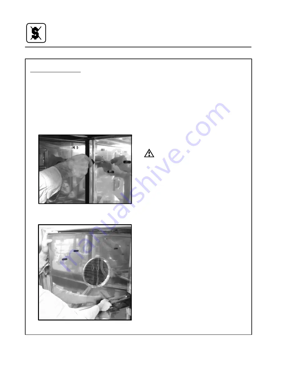
3. Rotate the two screws on the left side of the fan

guard.

Figure 14

4. Remove the fan guard.

Figure 15

5. Thoroughly  spray  cleaner  onto  the  fan  and

heat  source.  Close  the  doors  to  allow  the

cleaner to work.

6. After ten minutes, rinse the cleaner off. Return

the fan guard to the closed position. Rotate

the two screws to secure the fan guard.

Remove  and  clean  the  blower  wheel  every  6

months.

CLEANING THE EXTERIOR

The exterior of the appliance may be cleaned and

kept in good condition with a light oil. Saturate a

cloth and wipe the appliance when it is cold; wipe

dry with a clean cloth.

WARNING!!
DO NOT spray the outside of the appliance

with water or clean with a water jet. CleanĆ

ing with a water jet can impregnate chloĆ

rides into the  stainless steel, causing the

onset of corrosion.

PREVENTIVE MAINTENANCE

The  best  preventive  maintenance  measures  are

āāāthe āāāproper āāinitial āāinstallation āāof āāthe equipment and

a  program  for  cleaning  the  appliance  routinely.

The oven requires no lubrication. Contact the facĆ

tory, the factory representative or a local Blodgett

service company to perform maintenance and reĆ

pairs should they be required.

Summary of Contents for HV-100EM

Page 1: ...gett com 44 Lakeside Avenue Burlington Vermont 05401 USA Telephone 800 331Ć5842 802 860Ć3700 Fax 802 864Ć0183 PN 51702 Rev D 5 10 2009 G S Blodgett Corporation HVĆ100EM CONVECTION OVEN WITH MOISTURE INSTALLATION OPERATION MAINTENANCE ...

Page 2: ... ovens for every foodservice operation regardless of size application or budget In fact no one offers more models sizes and oven applications than Blodgett gas and electric fullĆsize halfĆsize countertop and deck conĆ vection Cook n Hold CombiĆOvens and the industry s highest quality Pizza Oven line For more information on the full line of Blodgett ovens contact your Blodgett representative ...

Page 3: ...INSTRUCTIONS THOROUGHLY BEFORE INSTALLING OR SERVICING THIS EQUIPMENT The information contained in this manual is important for the proper installation use and maintenance of this oven Adherence to these procedures and instrucĆ tions will result in satisfactory baking results and long trouble free service Please read this manual carefully and retain it for future reference Errors Descriptive typog...

Page 4: ...Your Service Agency s Address Model Serial Number Your appliance was installed by Your oven s installation was checked by ...

Page 5: ...ation 5 Oven Assembly 6 Supply Water and Plumbing 10 Electrical Supply 11 Operation MenuSelect Control 12 Maintenance Spray Bottle Operating Procedure 18 Cleaning and Preventive Maintenance 19 Replacement Parts 21 Second Level Programming 29 Troubleshooting 31 Sequence of Operation 33 Component Resistance Readings 35 Probe Ohms Chart 36 ...

Page 6: ...perienced kitchen staff to operate The Cool Down mode alĆ lows the oven cavity to cool down rapidly with the door opened Cleaning is kept to a minimum The interior is sprayed with a selfĆacting cleaning solution which interacts with humidity to easily remove crusts and stains The oven is designed for easy care and is welded water tight so that the internal cooking cavity may be rinsed with a hose ...

Page 7: ...s required and have complied with all requireĆ ments of state or local authorities having jurisdiction U S and Canadian Installations Reference National Electrical Code ANSI NFPA 70 Latest Edition and or Canadian Electrical Code CSA C22 1 as applicable This equipment is to be installed in compliance with the Basic Plumbing Code of the Building OffiĆ cials and Code Administrators International Inc ...

Page 8: ...tisfactory performance Certain minimum clearances must be maintained between the oven and any combustible or nonĆ combustible construction Oven body sides 0 0cm Oven body back 6 152 4cm In addition the following clearances are recomĆ mended for servicing Oven body sides 12 30cm Oven body back 12 30cm SHIPPING NOTE The following parts are shipped with the oven Part Description Qty R10955 Cleaning s...

Page 9: ...e equipment Damage sustained as a direct result of improper ventilation will not be covered by the Manufacturer s warranty When installed in the Commonwealth of MassaĆ chusetts this appliance must be interlocked with the hood exhaust system so that the appliance may be operated only when the hood exhaust sysĆ tem is running U S and Canadian Installations Refer to your local ventilation codes In th...

Page 10: ... LEG BOLTING PATTERNS There are two leg mounting options See Figure 1 35 00 2 PLACES 27 94 2 PLACES 36 19 2 PLACES 26 75 2 PLACES 875 8 PLACES 35 00 2 PLACES 36 19 2 PLACES 2 50 4 PLACES 313 8 PLACES 3 50 4 PLACES 56 HOLE 4 PLACES Figure 1 ...

Page 11: ...e leg and utility box with the two 3 4 bolts provided Utility Box Figure 3 5 Repeat steps 1 2 and 4 with the left front leg Figure 4 6 Tip the oven up on the newly installed front legs ā 7 Repeat āthe above steps for the right rear leg Install the retainer bracket before securing the right rear leg Align the holes in the retainĆ er bracket to the holes in the right leg plate See Figure 5 8 Secure ...

Page 12: ...the two screws from above and beĆ low the control panel Slide the panel out to acĆ cess the terminal blocks Figure 7 2 Connect the power cord to the top unit Run the cord down the back of the oven using the provided strain relief 3 Then route the cord under the oven supportĆ ing it on the retainer bracket on the rear right leg Connect to the top right receptacle on the utility box at the front of ...

Page 13: ...l drain Use the remaining piece of hose for the bottom oven if necessary See Figure 6 for location of drain connection on back of ovens Cavity Vent Extension 1 Attach the cavity vent extension using the siliĆ con tubing and two clamps provided 2 Remove the existing screw and use it to seĆ cure the top section in the bracket The tabs on the bracket will deflect for a secure fit Utility Supply Conne...

Page 14: ...ic water drain connection for City of Los Angeles 1 Each drain line from the appliance shall be routed without dips or sags to terminate above the flood level rim of an approved indirect waste receptor 2 The appliance shall be installed in accordance with the manufacturer s printed instructions and the LAPC and LAMC 1999 editions 3 A backflow protection device may be required by local codes If so ...

Page 15: ... have a minimum of 076 3mm contact spacing The circuit breaker must meet all Local and National installation standards All appliances must be installed in accordance with Local or National Electrical codes A wiring schematic is located in the slide out panel NOTE Disconnect the power supply to the apĆ pliance before servicing WARNING Improper installation may invalidate your warranty A strain reli...

Page 16: ...Ć press to enter steam mode 10 HOT AIR KEY Ć press to enter hot air mode 11 RETHERM KEY Ć press to enter retherm mode this mode uses steam to reheat frozen or precooked product Retherm has a temperĆ ature limit of 250Ć300 F 12 STEAM ON DEMAND KEY Ć used to initiate steam injection cycle 13 PROBE KEY Ć press to use core probe cooking 14 FAN KEY Ć press to select the fan speed 15 LIGHT KEY Ć press t...

Page 17: ...e desired percentage of steam NOTE Retherm has a temperature limit of 250Ć300_F 5 When the display flashes READY IDLE open the doors Load the product 6 Press the START STOP KEY 1 to begin the bake cycle The timer counts down and the display alternates between the cooking mode and the name of the product PROGRAMMED COOKING 1 Press the down arrow key until the name of the product is highlighted or u...

Page 18: ...d of the timed cycle the unit reverts back to the original setting Steam On DeĆ mand can be used at any time during the cook cycle 1 Press the STEAM ON DEMAND KEY 12 2 Use the arrows or the alpha numeric keypad to enter the desired steam on demand time Press OK to initiate Steam on Demand cycle NOTE Steam on Demand time is set in one minute increments using the arrows To set time in less than one ...

Page 19: ...enter the letter L press the 5 key three times 4 Press the PROG KEY 17 With SAVE highĆ lighted press OK to save the product name Programming a Product Recipe NOTE The control can hold 99 recipes Each recĆ ipe may have up to 6 cooking stages 1 Use the arrows to highlight the name of the product to be programmed Press OK to seĆ lect the product 2 The display reads PRODUCT NAME STAGE 1 Press OK to se...

Page 20: ...f auto is selected the program will use the deĆ fault fan cycle setting The default is set through the Manager Programming See page 17 8 Use the arrows to set the vent position Choose between OPEN or CLOSE Press OK to set the vent position 9 Use the arrows to scroll down to PRODUCT NAME STAGE 2 Press OK to select stage 2 10 Repeat steps 2Ć9 for all remaining stages 11 When all stages have been pro...

Page 21: ... OK to select Choose from the following functions Recipe Password Select YES or NO to enĆ able password protection on recipe programĆ ming If YES is selected the passcode 3124 must be entered to change recipe programĆ ming Temp Unit Select either degrees F or C Cool Down Temp Select the set temperaĆ ture for the oven to achieve in Cool Down mode Temp Disp Rate Set the rate in seconds at which the ...

Page 22: ...s the trigger with your thumb 4 Adjust spray nozzle for a wide spray pattern 5 After a period of spraying the pressure will drop Restore the pressure by operating the air pump 6 Release pressure after use by inverting the spray head and depressing the trigger or byā slowly āunscrewing ā theā spray āhead assembly āwhichā willā allow āairā toā escape āfrom around āāāthe filling aperture 7 Afterā use...

Page 23: ... solution manufacturer āForā āādifficult baked on grease etc allow to work over night 5 Set the timer for 15 to 20 minutes 6 Run āātheā āoven at 225 F 107 C in the Steam mode This will soften all burned on residue 7 Rinseāā āātheāāā āapplianceāāāāā interiorā āāāwithāāāāā waterāā a hose is supplied āā ābut āāātakeāā careā thatā only āātheā interior cavity is sprayed with water Wipe the interior dry...

Page 24: ...an guard to the closed position Rotate the two screws to secure the fan guard Remove and clean the blower wheel every 6 months CLEANING THE EXTERIOR The exterior of the appliance may be cleaned and kept in good condition with a light oil Saturate a cloth and wipe the appliance when it is cold wipe dry with a clean cloth WARNING DO NOT spray the outside of the appliance with water or clean with a w...

Page 25: ... JACK 5 M3367 NUT 6Ć32 KEPS QTY 4 6 5805 SCREW M 6Ć32 X 3 8 PNHD PH QTY 2 7 52574 DECAL MARINE NAVIGATIONAL PAD 8 51594 HARNESS HV100E FRONT CONTROL 9 52185 CIRCUIT BREAKER PANEL MOUNT 10 52647 USB CABLE 11 52600 SPACER USB 12 52161 COVER USB 13 38840 SCREW MACH 4Ć40 X 3 8 SS PAN HD MENUSELECT CONTROL Maintenance 21 Replacement Parts ...

Page 26: ...Y 2 6 51542 ASSEMBLY DOOR HANDLE 7 51539 PLATE LATCH COVER QTY 2 8 51668 GASKET DOOR LATCH QTY 2 9 16384 10Ć24 X 500 TRUSS HEAD MACH SCREW QTY 4 10 M6315 10Ć24 X 1 2 HEX WASHER HEAD SCREW S S QTY 4 11 50836 SCREW 10 24 X 2 00 FLATHEAD QTY 4 12 51559 ASSEMBLY RH OUTER DOOR 13 51556 ASSEMBLY RH INNER DOOR GLASS 14 51603 DOOR TURNBUCKLE ASSEMBLY 15 52514 DOOR SWITICH ASSEMBLY DOORS 15 Maintenance 22 ...

Page 27: ...TICAL DOOR QTY 2 7 51519 CLIP DOOR GLASS 8 16470 NAMEPLATE BLODGETT 10 INCH 9 51450 DOOR CHANNEL RH DOOR 10 51631 BUMPER HIGH TEMPERATURE QTY 6 11 R1278 RIVET 1 8 POP S S 12 16384 10Ć24 X 500 TRUSS HEAD MACH SCREW QTY 14 LH OUTERDOOR SUBASSEMBLY P N 51552 BREAKDOWN A B B SECTION A A SECTION B B 8 1 5 3 9 6 10 2 7 11 12 4 A Maintenance 23 Replacement Parts ...

Page 28: ... 7 51519 CLIP DOOR GLASS 8 51631 BUMPER HIGH TEMPERATURE QTY 6 9 R1278 RIVET 1 8 POP S S 10 16384 10Ć24 X 500 TRUSS HEAD MACH SCREW QTY 14 11 51541 CENTER GASKET CHANNEL INNER 12 52475 GASKET RETAINER OUTER 13 51610 GASKET CENTER DOOR RH OUTERDOOR SUBASSEMBLY P N 51559 BREAKDOWN SECTION A A SECTION B B A B B A 2 12 13 11 1 6 7 9 10 8 5 3 4 Maintenance 24 Replacement Parts ...

Page 29: ...LATE FAN BRACKET COVER 4 R4244 SHAFT SEAL 5 R8955 SEAL RETAINER 6 39332 MOTOR 220V 1 2 HP 7 R1971 SPACER RACK GUIDE QTY 4 8 R0726 WASHER LOCK 10 QTY 4 9 R1539 10Ć32 X 50 HXWHD MACHINE SCREW QTY 4 10 8628 NUT 5 16 Ć18 SERRATED FLANGE QTY 4 MOTOR 3 5 2 10 6 7 1 4 8 9 Maintenance 25 Replacement Parts ...

Page 30: ...7 BRACKET INVERTER DRIVE 8 38605 TERMINAL BLOCK 3 POLE 9 51122 BRACKET COOLING DIVIDER 10 52535 ASSY WATER MANIFOLD NAVY 11 51435 BRACKET POWER SUPPLY SLIDE 12 15847 GROMMET RUBBER 11 16 13 51489 BRACKET I O BOARD 14 51948 INTERFACE BOARD ELECTRICAL PANEL 45 46 47 48 49 50 51 6 25 26 10 27 33 16 5 4 11 1 19 30 9 24 38 43 42 28 2 38 15 34 40 41 3 17 39 14 13 23 7 31 8 20 18 32 2 Maintenance 26 Repl...

Page 31: ... 52446 CIRCUIT BREAKER W TRIP COIL 25A 3 POLE 30 R5770 SCREW 1 4Ć20 X 50 PANHEAD QTY 2 31 37951 SCREW MACHINE PAN HEAD 4Ć40 X 1 00 QTY 2 32 4068 GROMMET BLACK RUBBER 33 R5056 CUSHION CLAMP 34 52680 INVERTER DRIVE J1000 PROGRAMMED 37 39914 SCREW 8Ć32X1 2 TRUSS HEAD QTY 2 38 R11090 ENDSTOP DIN RAIL QTY 2 39 52706 RESISTOR MOTOR BRAKING 40 15772 SERIAL TAG 41 R1278 RIVET 1 8 POP S S QTY 2 42 52717 CO...

Page 32: ...6 53016 220V ELEMENT 440V OVEN 53015 240V ELEMENT 480V OVEN 7 52304 ELEMENT GASKET 8 51623 RACK SUPPORT 9 52307 CAVITY PROBE 10 50020 SPRAY TUBE 11 51488 DOOR CATCH 12 52716 PERIMETER DOOR GASKET 13 36441 HIĆLIMIT PROBE 14 D0127 LIGHT GASKET 15 39324 CAVITY VENT SOLENOID INTERIOR COMPONENTS Maintenance 28 Replacement Parts ...

Page 33: ... Scroll to Exit Press Ok Scroll to Service Press Ok Enter Service Code 7378 Press Ok Scroll to Diagnostic Output Press Ok Press and hold each button below to test the function listed on the right Component Tested See Trouble Shooting Test Points for output testing if necessary Temp Heat On Fan High Fwd Hot Air Hot Air Enable Hot Air Contactor Combi Fan Speed Gentle Forward 20 Hz Fan Fan Speed Low ...

Page 34: ...old each button beĆ low to test the input listed on the right Input Tested Temp Fan Error Open or Closed Drive At Speed Relay Combi Door Open or Closed Door Switch Fan Cavity Probe Temp Prog Cooling Fan Probe Temp 4 Core Probe Temp Open if not inserted Press Ok to Exit Press Esc to Exit Press Esc to Exit ...

Page 35: ...6ĆPin 8ĆBL Wire 24VDC Temp Heat On Fan High Fwd Hot Air Hot Air Enable Hot Air Contactor Hot Air Contactor Terminal Block 4 Pin 4 Connector J20ĆPin 2ĆOR Wire 24VDC 7 Light Terminal Block 4 Pin 4 Connector J3ĆPin 4ĆRD Wire 24VDC Light Spritzer Terminal Block 4 Pin 4 Connector J18ĆPin 3ĆVI Wire 24VDC Esc Cooling Fan Terminal Block 4 Pin 4 Connector J3ĆPin 11ĆGY Wire 24VDC 2 Vent Terminal Block 4 Pin...

Page 36: ... 1 Fan Speed Turbo Forward 50 Hz J2 9Ć12 See Chart Below Terminal Block 4 Pin 4 24VDC 4 Fan Speed High Reverse Ć40 Hz J2 9Ć12 See Chart Below Terminal Block 4 Pin 4 24VDC Output Components J2 9 Bit 0 J2 10 Bit 1 J2 11 FWD J2 12 REV Gentle Forward Outputs 20 Hz 0v 0v 23Vdc Rtn 0v Low Forward Outputs 30 Hz 23Vdc Rtn 0v 23Vdc Rtn 0v High Forward Outputs 40 Hz 0v 23Vdc Rtn 23Vdc Rtn 0v Turbo Forward O...

Page 37: ...e K2 relay at J6 7 The K2 relay waits for input from the Fan Speed or Drive Set Speed Relay which is 24 VDC return at the grey wire in J11 4 D35 LED shows the Hot Air Enable relay is actiĆ vated when the Fan Speed Relay is closed at the Inverter sending 24 VDC return in at J11 4 this sigĆ nal closes K2 Check for 24 VDC output at J6 8 on the blue wire which jumps to J20 1 J20 1 is the common to the...

Page 38: ...he Water Spritzer is called for D33 is lit and K8 sends out 24 VDC on the Violet wire at J18 3 Steam uses the same call for heat and the Spritzer is cycled at 100 In steam the lowest temperature setting is 85 F and the maximum temperature in the steam mode is 225 F Steam on demand is not available in Steam mode because the control is cycling the Spritzer at 100 already Retherm uses the Water Sprit...

Page 39: ...nt Single element 24 Element At contactor 32 5 Heating Contactor Coil 6 Water Solenoid Valve 178 Cooling Fan 3 7 Part Name Ohms Convection Motor Windings Blue to Black 6 2 Connection Motor Windings Brown to Black 6 2 Connection Motor Windings Brown to Blue 6 2 Circuit Breaker Trip Coil 3 7 Vent Solenoid 30 Step Down Transformer Primary 2 Step Down Transformer Secondary 1 NOTE Readings may vary som...

Page 40: ...tenance 36 Probe Ohms Chart Temp Probe Ohms P N 51516 0 1000 20 1078 24 1090 30 1115 50 1195 60 1232 80 1310 93 1360 Temp Probe Ohms P N 51516 100 1386 120 1460 150 1575 180 1685 200 1758 230 1868 260 1978 ...

Page 41: ......

Page 42: ......

Page 43: ......

Reviews: