background image

Charge on.


BlinkCharging.com


Page 45 of 56 

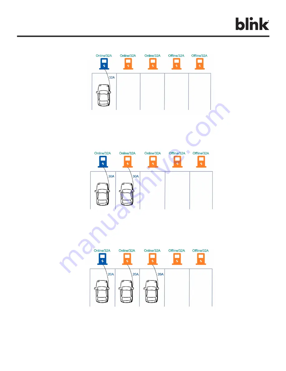
With one connected vehicle, the charging current is 32A. (Reserve 20A for offline charging stations) 


Figure 36. Example 3 – One Connected Vehicle 

With two connected vehicles, the charging currents are evenly reduced to 30A. (Reserve 20A for offline 
charging stations) 


Figure 37. Example 3 – Two Connected Vehicles 

With three connected vehicles, the charging currents are further reduced to 20A. (Reserve 20A for offline 
charging stations) 


Figure 38. Example 3 – Three Connected Vehicles  


Summary of Contents for MQ 200

Page 1: ...BlinkCharging com INSTRUCTION MANUAL Blink MQ 200 Level 2 AC EVSE Version 1 0 ...

Page 2: ...ns general guidelines and may not provide instructions for your specific situation Do not attempt installation if you lack the knowledge and understanding required for the installation otherwise personal injury and or death as well as property damage or loss could occur Electricity is dangerous and can cause personal injury or death as well as other property loss or damage if not used or construct...

Page 3: ...WIRE SIZE TEMPERATURE 10 6 4 PRODUCT INSTALLATION 11 7 GETTING STARTED 16 7 1 BROWSER ACCESS 16 7 2 WEB PAGE OVERVIEW 17 7 3 CONFIGURATION 20 7 4 MAINTENANCE 38 7 5 LLM STATUS 39 7 6 SECURITY 49 8 DISPLAY 50 8 1 CHARGING STATE DISPLAY 50 9 OPERATIONS 51 9 1 CHARGING STATUS INDICATORS 51 9 2 AUTHORIZATION 51 9 3 START CHARGING 52 9 4 STOP CHARGING 53 10 GENERAL CARE 54 11 SUPPLEMENTAL INFORMATION 5...

Page 4: ...minal connectors for field wiring connections shall be provided with instructions specifying a range of values or a nominal value of tightening torque to be applied to the clamping screws of the terminal connectors Make sure that the materials used and the installation procedures follow local building codes and safety standards The information provided in this manual in no way exempts the user of ...

Page 5: ...rd or EV cable is frayed has broken insulation or any other signs of damage Do not use this product if the enclosure or the EV connector is broken cracked open or shows any other indication of damage WARNING RISK OF ELECTRIC SHOCK Improper connection of the equipment grounding conductor can result in a risk of electric shock Check with a qualified electrician or serviceman if you are in doubt as t...

Page 6: ... Product voids the manufacturer s warranty The Blink Product specified in this document is design for the North American market to charge plug in electric vehicles PEVs plug in hybrid electric vehicles PHEVs and battery electric vehicles BEVs It provides level 2 AC charging that shortens the charging time for typical EVs when compared to a Level 1 AC EVSE 3 PRODUCT OVERVIEW MODEL NAME MQ 200 MODEL...

Page 7: ...cal Area Network LAN 2 4 and 5 GHz Wi Fi 802 11 b g n ac Wide Area Network WAN Cellular 4G LTE AGPS PTCRB SAFETY COMPLIANCE SPECIFICATIONS Ground Fault Detection CCID20 20 mA per UL 2231 Automatic Reset Feature and Manual Reset Feature Ground Monitor Ground Monitor per UL 2231 Safety Compliance UL and cUL NEC Article 625 RoHS Protection Over Voltage OVP Under Voltage UVP Over Current OCP Over Temp...

Page 8: ...ndards Before installing the Blink Product review this manual carefully and consult with a licensed contractor licensed electrician and trained installation expert to ensure compliance with local building practices climate conditions safety standards and state and local codes Use appropriate protection when connecting to the main power distribution cable Use tools as outlined in the Tools Required...

Page 9: ...ge Drop 24A 30A Two 8AWG Wires Line One 10AWG Wire Ground 3 4 1 150ft One Way Distance 3 Voltage Drop 32A 40A Two 8AWG Wires Line One 10AWG Wire Ground 3 4 1 150ft One Way Distance 3 Voltage Drop 40A 50A Two 6AWG Wires Line One 8AWG Wire Ground 3 4 1 150ft One Way Distance 3 Voltage Drop 48A 60A Two 4AWG Wires Line One 8AWG Wire Ground 1 1 150ft One Way Distance 3 Voltage Drop 50A 70A Two 4AWG Wir...

Page 10: ...Models Notes MQ 200 Charger 50 A 1 All Product Models Included Mounting Bracket 1 All Product Models Included Mounting Screws Wood 5 16 2 Commercially Available Commercially Available Mounting Anchors Masonry 5 16 4 Commercially Available Commercially Available Conduit Fitting 1 1 Commercially Available Commercially Available Conduit 1 As Needed Commercially Available Commercially Available Table ...

Page 11: ...11 of 56 6 4 Product Installation STEP 1 Remove front cover screws STEP 2 Remove the front cover STEP 3 Remove the installation cover screws STEP 4 Remove installation cover Figure 1 Exploded View of MQ 200 Charger Figure 2 DIP Switch ...

Page 12: ...12 of 56 STEP 5 Set maximum current by configuring the DIP switch using the following table Table 7 DIP Switch Configuration WARNING Power must remain off before setting or configuring the DIP switch Note will be available in MP phase ...

Page 13: ... stored or located at a sufficient height above the floor For an indoor site it should be not lower than 18 450 mm and not higher than 4 1 2m For an outdoor site it should be not lower than 24 600 mm and not higher than 4 1 2m Refer to Article 625 NEC The mounting bracket has six screw holes for wall mounting If only two screws are used for mounting the screws should pass through the middle two sc...

Page 14: ...commercially available B For finished walls supported by wood studs use 12 self tapping screws C Please refer to the following torque The actual torque is according to the wall material Screw Torque M6 25 kgf cm min 21 7 lb in min 12 25 kgf cm min 21 7 lb in min Table 8 Mounting Bracket Torque Values M6 Screw ScrewScre w ...

Page 15: ...r and Mounting Bracket STEP 8 Hang the product on the mounting bracket STEP 9 Slide down the product to rest on the bottom flange STEP 10 Install the locking screws M4 Torx STEP 11 Reassemble the Install Cover and Front Cover with M4 screws using 15 kgf cm 12 lb in ...

Page 16: ...n access the charger by Wi Fi using a phone or computer The Wi Fi network name SSID is a number on the label on the side of the EVSE Please refer to Figure The SSID name is IC80A SN The default password is SN IC80A Ex SN Ex 1193 1A13 1 1234 2444 The SSID name is IC80AEx 1193 1A13 1 1234 2444 The password is Ex 1193 1A13 1 1234 2444 IC80A Figure 6 Serial Number Location on Main Label ...

Page 17: ...er and press enter The login screen appears as in Figure below Figure 7 Web Portal Screen Enter admin in the user name box The default password is howru2RU2IC3 7 2 Web Page Overview 7 2 1 Menu Overview To navigate via the web browser use the menu items available Configuration Maintenance EVSE Status LLM Status and Security shown in the figure below Figure 8 Menu Overview ...

Page 18: ... Settings tab is used to set up the custom properties for uses in OCPP 1 6 services The Communication Settings tab is used to set up the network connection and load management 7 2 3 Maintenance Menu When you choose the Maintenance menu a sub menu will appear in the figure below Figure 10 Menu Overview Maintenance The Command screen can be used to restart the EVSE and reset settings to Manufacturin...

Page 19: ...rview LLM Status The Local Load Management Status screen shows the Local Load Management LLM settings and current Master Slave group member list 7 2 4 Security Menu When you choose the Security menu a sub menu will appear in the figure below Figure 12 Menu Overview Security The Change Password screen can be used to change the password of users for this web portal ...

Page 20: ...vendor s name of the EVSE EVSE Model The model s name of the EVSE EVSE Serial Number The unique serial number of the EVSE Firmware Version The software version of the EVSE Production Date The production date of the EVSE Charging Connector Information Number of Connectors Number of connectors of the EVSE Connector Type Indicates type 1 or type 2 cable installed in the EVSE Max Amperage Connector Th...

Page 21: ...figuration and then Station Settings link will bring up the following screen shown below in the figure below On this page you can change the properties of the EVSE Click the Apply button at the right side of the property when the value is changed Figure 14 Configuration Station Settings ...

Page 22: ...the EVSE is online This signal is to tell EV how much current is allowed to use Real Amperage The real time charging current detected by the EVSE Cold Load Pickup Max Delay Default cold load pickup delay is 120s 720s The max value could be changeable by this property Plug and Charge ID If the value is present the EVSE needs to support plug and charge scenario by using the specific identifier If ab...

Page 23: ...ge on BlinkCharging com Page 23 of 56 Default price and station location information are shown in the figures below Figure 15 Station Setting Default Price Settings Figure 16 Station Setting GPS Information ...

Page 24: ...Figure 17 Configuration OCPP Settings On this page you can change the properties just for the EVSE Click the Apply button at the right side of the property when the value is changed Remote Service Settings Remote Service Type The remote control mode accepted by charger Options are APP Charger is controlled by mobile APP OCPP Charger is controlled by OCPP 1 6 protocol ...

Page 25: ...ransport layer of the OCPP service that will be used The available option is WS and WSS WS Connection from EVSE to OCPP Server uses WebSocket protocol WSS Connection from EVSE to OCPP Server uses Secure WebSocket protocol Boot Notification Interval Interval of re sending BootNotification req if not accepted by Central System Boot Notification Retries Number of times to retry sending BootNotificati...

Page 26: ...imum intensity at which to illuminate the EVSE lighting This value is not changeable for IC SC LocalAuthorizeOffline Whether the EVSE when offline will start a transaction for locally authorized identifiers LocalPreAuthorize Whether the EVSE when online will start a transaction for locally authorized identifiers without waiting for or requesting an Authorize conf from Central System MaxEnergyOnInv...

Page 27: ...on TSR Reversed 120 degree rotation ConnectorPhaseRotationMaxLength Maximum number of items in a ConnectorPhaseRotation configuration key StopTransactionOnEVSideDisconnect When set to true the EVSE SHALL administratively stop the transaction when the cable is unplugged from the EV StopTransactionOnInvalidId Whether the EVSE will stop an ongoing transaction when it receives a non accepted authoriza...

Page 28: ... SC since it is plug type and no connector locker WebSocket Ping Interval Define the ping pong interval for WebSocket protocol LocalAuthListEnabled Whether the Local Authorization List is enabled LocalAuthListMaxLength Maximum number of identifications that can be stored in the Local Authorization List SendLocalListMaxLength Maximum number of identifications that can be send in a single SendLocalL...

Page 29: ...mmand to proper client EVSEs or Gateway itself NOTE A Gateway EVSE can choose using Wi Fi Cellular Ethernet to connect to the internet by changing Group Use External Gateway setting If set to Yes a Gateway will use Cellular Wi Fi Ethernet When changed this setting the Connectivity option will automatically change as well All EVSE in this Gateway Client group must have the same Group Use External G...

Page 30: ...ue is Auto Gateway Serial Number The serial number of the EVSE which acts as a Gateway Gateway LAN IP The IP of master in LAN This value cannot be modified by users Max Group Size The maximum number of EVSEs allowed in a group LAN is 20 This value cannot be modified by users Hide AP SSID Options for hiding SSID of this EVSE or not For IC SC this option is always off ...

Page 31: ...o the Internet via Ethernet Figure 21 Internet Connection via Ethernet Setting up each EVSE according to the following settings Setting Gateway Client Network Mode Gateway Client Group Use External Gateway Yes Yes Connectivity Ethernet Ethernet Client Connectivity None None Gateway Serial Number Gateway Serial Number Gateway Serial Number Table 9 Ethernet Gateway Client Settings ...

Page 32: ...igure 22 Internet Connection via Wi Fi Set up each EVSE according to the following settings Setting Gateway Client Network Mode Gateway Client Group Use External Gateway Yes Yes Connectivity Wi Fi Wi Fi Client Connectivity None None Gateway Serial Number Gateway Serial Number Gateway Serial Number Table 10 Wi Fi Gateway Client Settings ...

Page 33: ...etwork Mode Gateway Client Group Use External Gateway No No Connectivity Wi Fi Cellular Wi Fi Client Connectivity Wi Fi None Gateway Serial Number Gateway Serial Number Gateway Serial Number Table 11 Wi Fi or Cellular Gateway Client Settings Active Device Status Active Device Current active network device Possible values are None Ethernet Wi Fi or Cellular Active IP Address Current active IP addre...

Page 34: ...ault Gateway fields IP Address The IP address of the EVSE It s modifiable if Link Mode is Static IP Netmask The subnet mask It s modifiable if Link Mode is Static IP Default Gateway The default gateway It s modifiable if Link Mode is Static IP Primary DNS The primary Domain Name Server optional Secondary DNS The secondary Domain Name Server optional Ping URL Address of the host that the EVSE will ...

Page 35: ...ipment Identifier of the modem Cellular APN This is the gateway for all cellular traffic Contact your cellular operator for information about this For AT T and Verizon LTE service just leave it blank since the apn name is built in in the modem APN Username This is the username your ISP has assigned to you optional APN Password Password to log into the ISP network optional Dial Number Phone number ...

Page 36: ...ent limit from Gateway If disconnection occurred between a Client and Gateway then the Client will use fallback value as the limitation Local Load Management Enable or disable Local Load Management function This function can only be enabled in a Gateway or Client EVSE HINT If user changes Network Mode setting then related settings will also change automatically such as Connectivity Local Load Mana...

Page 37: ...ct to Gateway Group Size The total number of EVSEs in the LLM group This value is only used in Gateway Max Amperage Grid Connection Total ampere of each phase allowed loading for the group of EVSEs at the same time This value is only used in Gateway Fallback Current The fallback current when Client is not able to communicate with Gateway Gateway will overwrite fallback current in Client with its o...

Page 38: ...work settings maximum amperage to the manufacturer default values DIP Switch Reset Power off the unit and configure DIP switch into the off position shown below in figure 30 Table 13 Reset Factory Default DIP Switch Configuration Charging Profile Data HINT Local authorization is defined in OCPP 1 6 specification There are two local lists Local Authorization List and Authorization Cache List The Lo...

Page 39: ...ersion downgrading firmware may cause unpredicted problem and is not recommended 7 5 LLM Status 7 5 1 LLM Information This page shows the Local Load Management information of the EVSE For more LLM description please refer to section 7 5 3 Network Operation Mode Indicates the EVSE is in Direct mode a Gateway or a Client LLM Mode Indicates Local Load Management function is enabled or disabled Networ...

Page 40: ...LLM group of each EVSE Wire Type The power source wire type of each EVSE Request The requested current of each EVSE PWM The PWM charger allowed current of each EVSE Phase 1 Phase 2 Phase 3 The real current loaded by the vehicles of each EVSE 7 5 3 Operation Mode There are two different operation modes Distribution mode and Priority mode Each time when a new coming car is plugged in and start charg...

Page 41: ...ng up each charging stations according to the following settings Setting Gateway Client Local Load Management Enable Enable Charging Policy Uniform Distribution Not used Group ID LLM Group 1 LLM Group 1 Same as Gateway Group Size 3 Not used Max Amperage Grid Connection 60 Not used Fallback Current 10 10 Same as Gateway Table 14 Example 1 LLM Settings With one connected vehicle the charging current...

Page 42: ... With two connected vehicles the charging currents are evenly reduced to 30A Figure 31 Example 1 Two Connected Vehicles With three connected vehicles the charging currents are further reduced to 20A Figure 32 Example 1 Three Connected Vehicles ...

Page 43: ...ent Enable Enable Charging Policy Uniform Distribution Not used Group ID LLM Group 1 LLM Group 1 Same as Gateway Group Size 3 Not used Max Amperage Grid Connection 60 Not used Fallback Current 10 10 Same as Gateway Table 15 Example 2 LLM Settings With one connected vehicle the charging current is 32A Figure 33 Example 2 One Connected Vehicle With two connected vehicles the charging currents are ev...

Page 44: ...is example there are five 32A charging stations in the LLM group and two of the charging stations are offline Setting up each charging station according to the following settings Setting Gateway Client Local Load Management Enable Enable Charging Policy Uniform Distribution Not used Group ID LLM Group 1 LLM Group 1 Same as Gateway Group Size 5 Not used Max Amperage Grid Connection 80 Not used Fall...

Page 45: ...ple 3 One Connected Vehicle With two connected vehicles the charging currents are evenly reduced to 30A Reserve 20A for offline charging stations Figure 37 Example 3 Two Connected Vehicles With three connected vehicles the charging currents are further reduced to 20A Reserve 20A for offline charging stations Figure 38 Example 3 Three Connected Vehicles ...

Page 46: ...e A In this example there are three 32A charging stations in the LLM group Setting up each charging stations according to the following settings Setting Gateway Client Local Load Management Enable Enable Charging Policy First In First Serve Not used Group ID LLM Group 1 LLM Group 1 Same as Gateway Group Size 3 Not used Max Amperage Grid Connection 60 Not used Fallback Current 10 10 Same as Gateway...

Page 47: ...gure 40 Example A Two Connected Vehicles The third vehicle is NOT able to receive current Figure 41 Example A Three Connected Vehicles When the first vehicle left the second vehicle would receive 32A and the third vehicle would receive 28A Figure 42 Example A Two Remaining Vehicles ...

Page 48: ... Charging Policy First In First Serve Not used Group ID LLM Group 1 LLM Group 1 Same as Gateway Group Size 5 Not used Max Amperage Grid Connection 100 Not used Fallback Current 10 10 Same as Gateway Table 18 Example B Priority Mode LLM Settings The first vehicle connected would receive 32A Reserve 20A for offline charging stations Figure 43 Example B One Connected Vehicle The second vehicle would ...

Page 49: ...Security 7 6 1 Change Password To change password first choose user you want to change password There are two default users admin and maintain Only admin user can access Security Page Enter old password and new password then press Apply button to change password of the user To reset password of all users press Reset password of all users button Figure 46 Change Password ...

Page 50: ...e SUSPENDEDEVSE When the contactor of a Connector opens upon request of the EVSE e g due to a smart charging restriction or as the result of StartTransaction confindicating that charging is not allowed Operative SUSPENDEDEV When the EVSE is ready to deliver energy but contactor is open e g the EV is not ready FINISHING When a charging session has stopped at a Connector but the Connector is not yet...

Page 51: ...Flashing Green Slow Suspend Occupying Blue Flashing Flashing Blue Slow Charging Red Steady Unrecoverable Fault Red Flashing Recoverable Fault Pink Steady Reserved from OCPP Service Yellow Steady Power On Device Unavailable Yellow Flashing Booting Firmware Upgrading Out of Service Table 20 LED Status Indicators 9 2 Authorization Before the owner of an electric vehicle can start or stop charging the...

Page 52: ...ly supply energy after authorization Figure 47 Online Authorization 9 2 2 Local Authorization Synchronized with the Central System when EVSE is Online To improve the experience for users the EVSE MAY support local authorization when EVSE is offline and faster authorization response time when communication between EVSE and Central System is slow Figure 48 Local Authorization 9 3 Start Charging ...

Page 53: ...f the temporary error condition returns to normal Status indicator lights remain flashing RED until the error condition is resolved Temporary error conditions include Over Current Over Voltage Under Voltage and Over Temperature For Over Current conditions The charging session will be stop while OC occurs After recovery from OC for 30 seconds the EVSE will automatically restart charging for three t...

Page 54: ...es Despite the water resistance of the enclosure when cleaning it is preferred to not direct streams of water at the unit Clean with a soft damp cloth Make sure the charging plug is put back in the holster after charging to avoid damage Ensure the power cable is stored on the EVSE after use to avoid damage If the power cable or the charging plug is damaged please contact Customer Support ...

Page 55: ...ye connected In a Wye connected secondary installation use two of the legs to provide 208V to the charger For example L1 and L2 or L1 and L3 or L2 and L3 The two phases utilized must each measure 120V ground Note a current carrying neutral is not required for charger installation The center point of the three phases used as neutral must be single point grounded ...

Page 56: ...V to ground Note the charger s contactor closes only if it detects the presence of an earth ground wire connected to a neutral point on the transformer secondary 12 Customer Support Please contact your reseller directly for technical support The third leg A in the illustration of the delta transformer is 208V to neutral and is sometimes referred to as a high leg Do not use this third leg Do not us...

Reviews: