Blastrac BMG-2500, Operation And Maintenance Manual
The Blastrac BMG-2500 is a powerful and versatile floor grinder that delivers exceptional performance. Ensure optimal operation and maintenance of your machine by downloading the free Operation And Maintenance Manual from manualshive.com. This comprehensive manual will help you get the most out of your equipment for long-lasting results.
Share
Download


Reviews:
No comments
Related manuals for BMG-2500

GA5010
Brand: Makita Pages: 9

GA4040
Brand: Makita Pages: 12

GD0603
Brand: Makita Pages: 8
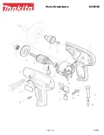
GV5000
Brand: Makita Pages: 2

DGA417
Brand: Makita Pages: 23

GA4041C
Brand: Makita Pages: 116

GA4034
Brand: Makita Pages: 11

GA7010C
Brand: Makita Pages: 6

DGA404
Brand: Makita Pages: 14

BGA402
Brand: Makita Pages: 12

9566C
Brand: Makita Pages: 10

9564PC
Brand: Makita Pages: 10

9564PC
Brand: Makita Pages: 3

9564HR
Brand: Makita Pages: 14

9561CR
Brand: Makita Pages: 9

GA7021
Brand: Makita Pages: 84

GA7020
Brand: Makita Pages: 2

9556HN
Brand: Makita Pages: 8


