background image


SERVSWITCH MULTIVIDEO INSTALLATION AND OPERATIONS MANUAL


24 

When all needed CPU ports have been pre-configured, the computers can 
be connected.  Perform the following for each computer to be connected: 
 
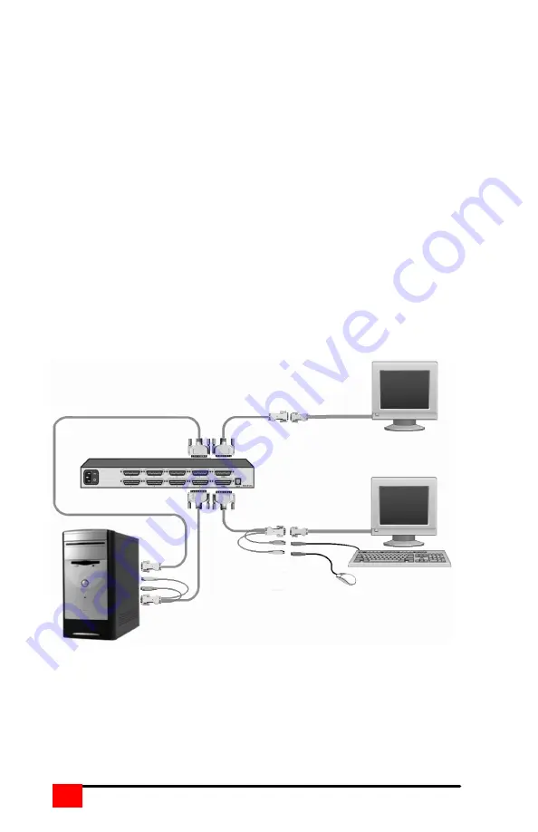
(Refer to the Troubleshooting section if needed and Figure 8 for a example 
of a single unit installation) 
Steps 
1.  Turn on the KVM stations monitor and apply power to the ServSwitch 

MultiVideo. 

2.  Wait until the “SELECT 1” LED on the front panel lights. 
3.  Switch the ServSwitch MultiVideo to CPU port x. (Ctrl,port #,[Enter]) 

(Starting with x = 1) 

4.  Connect the computer to the CPU port being configured using the 

appropriate CPU cable. 

5.  Connect the additional CPU video outputs to the corresponding 

connector on the ServSwitch MultiVideo using the appropriate cable. 

6.  Boot the computer, if needed.  You should see the boot-up sequence on 

the KVM monitor.  If the computer was connected to a pre-configured 
CPU port with power applied, you should see that computers video. 

7.  Switch to the next CPU port to connect a computer to as defined in step 

3 and perform steps 4, 5 and 6 for this computer and for then for the 
remaining CPU ports. 


Figure 8. SW0402A Unit installation 


Dual-Video CPUs (1-4) 

Video 1              

Video 2              

Summary of Contents for ServSwitch KV0202A

Page 1: ......

Page 2: ...ial area is likely to cause interference in which case the user at his own expense will be required to take whatever measures may be necessary to correct the interference Changes or modifications not...

Page 3: ...8 Selecting a computer using keyboard commands 28 Firmware update 29 Safety and EMC Regulatory Statements 34 Figures Figure 1 ServSwitch MultiVideo models 4 Figure 2 Rear panel 5 Figure 3 Main Menu 10...

Page 4: ...e user KVM switching for CPUs with multi video outputs The ServSwitch MultiVideo is the result of our commitment to providing state of the art switching solutions for today s demanding workplace The S...

Page 5: ...tform n Pre configuration feature allows for the installation of most computers or servers without removing power n Full keyboard and mouse emulation for automatic and simultaneous booting n Flash mem...

Page 6: ...expansion cables KVM station A KVM station consisting of a keyboard monitors and mouse connects to the rear panel DB25F connector labeled KVM1 CPU connection All CPU connectors on the ServSwitch Multi...

Page 7: ...deo models Label Description Power Power LED Green when unit is on LEDs Indicator LEDs Numbered pairs of LEDs shows status and power of connected computers and Switches Connects to the previous CPU Co...

Page 8: ...sis Figure 2 Rear panel Label Connector Description Power Mini Chassis only DIN 5F Power adapter connector None Slim and Full Chassis only IEC320 Power receptacle w switch X 1 2 mini 1 4 slim 1 4 8 fu...

Page 9: ...ultiVideo to CPU cables A CPU cable is used to connect each computer to the ServSwitch MultiVideo The CPU cable connects from the DB25F CPU ports on the ServSwitch MultiVideo to the keyboard video and...

Page 10: ...switching to next CPU port in scan mode Set mode Ctrl Mnn Enter where nn mode value from Table 4 Alternate way to configure keyboard and mouse Null mouse command Ctrl N Used to re sync a PS 2 mouse Re...

Page 11: ...ft 7 bit 8 CPU mouse Reserved for future use 9 CPU mouse 3 button serial Mouse systems 10 CPU mouse PS 2 wheel 11 CPU Keyboard mouse USB PC MAC 12 CPU Keyboard mouse USB Sun 20 Keyboard PC 101 102 PC...

Page 12: ...itional keystrokes will be sent to the selected computer and not the ServSwitch MultiVideo 3 Use only the numeric keys above the keyboard and not the numeric keypad 4 Letter commands such as Ctrl M ar...

Page 13: ...rvSwitch MultiVideo re establishes communication with the connected CPU The main configuration menu is accessed from the keyboard by pressing and releasing the left control Ctrl key and within 2 secon...

Page 14: ...settings or typematic rate delay and the Sun language settings ServSwitch Ultra Multivideo Keyboard and mouse type KVM station To configure the keyboard or mouse type use the up down arrow keys and se...

Page 15: ...256 Expansion width The Expansion width setting determines how many computers are connected to a slave unit If the slave units are 4 port units the width value would be 4 If they are 8 port units the...

Page 16: ...sents the Rate keys sec needed and press enter Delay This setting is for PC keyboards only It is used to adjust how long after a key is depressed and held that key starts to repeat To change the delay...

Page 17: ...s reference list To change the computer name select the Computer name to change and press enter An input box will display Enter the new computer name and press enter Keyboard To change a computers key...

Page 18: ...15 Save the changes when finished configuring each computer The keyboard and mouse selections are Keyboard choices Mouse choices PC1 PS 2 PC2 PS 2 wheel PC3 Serial 2 button USB PC Serial 3 button USB...

Page 19: ...verlay Miscellaneous Color scheme The default setting is Aquarium To change this select Color scheme and press enter A selection box will appear listing the 4 choices Use the arrow keys to select a sc...

Page 20: ...e up down arrow keys to select a new screen saver and press enter The default screen saver is Fireflies The choices are Black screen Fireflies Weaving Bounce Screen saver time seconds This sets the ti...

Page 21: ...e color choices are the same as the background selections Computer label The Computer label section allows you to customize the display of the computer label The colors position fade out time font and...

Page 22: ...d press enter A YES NO box will display Use the up down arrow keys and select either YES or NO and press enter Fade out seconds This controls how long the computer label displays before disappearing A...

Page 23: ...the configuration menu is called up Ctrl F12 this password must be entered Access password This feature is used to restrict unauthorized access to the connected computers To assign an access password...

Page 24: ...ord or power adapter Carefully remove the top chassis cover exposing the PCB Put a jumper on the two pins labeled Password reset jumper and power on the switch Call up the configure security menu and...

Page 25: ...system as having 8 CPU ports CPU ports 5 8 are blind ports If you program the expansion width to 4 then only CPU ports 1 4 on the 8 port Slave units can be accessed In systems that have a mixture of...

Page 26: ...the connected CPUs If removing power from a computer is not feasible the ServSwitch MultiVideo should be pre configured if needed before the CPU is connected The default keyboard and mouse types set f...

Page 27: ...t x Ctrl port Enter Starting with x 1 4 Connect the computer to the CPU port being configured using the appropriate CPU cable 5 Connect the additional CPU video outputs to the corresponding connector...

Page 28: ...U ports no mixed models then you can count the CPU ports used to connect to the computers The ports on the master unit used for expansion should not be counted If there is a mixture of models in the s...

Page 29: ...to by pressing and releasing the left control Ctrl key type in the CPU port number starting with port 1 and press Enter 3 Connect the computer to the CPU port using the appropriate CPU cable If the co...

Page 30: ...pe 4 Boot the computer if power was not applied You should see the boot up sequence on the KVM monitor If the computer was connected with power applied you should see that computer s video 5 Verify th...

Page 31: ...y then the or key will advance forward or backwards one sequential port Selecting a computer through the RS232 port Selecting a computer can be done through the RS232 port if needed Contact Black Box...

Page 32: ...press and release the left control Ctrl key then press the I key and the program version will display To update the firmware first download the latest revision from our web site and save it to a stan...

Page 33: ...fy the communication program is configured correctly Enter Y to try upgrading the flash again If programming is unsuccessful the unit should be serviced Method 2 Using the front panel switches with a...

Page 34: ...as removed for less than three seconds possibly causing keyboard to lock up Disconnect and re connect the keyboard If PS 2 type keyboard and mouse cables may be reversed Not using left control key Usi...

Page 35: ...e if necessary Video not synchronized or wrong color Cable is loose reseat cable Monitor not capable of syncing to video selected upgrade monitor Cable is defective try using cable from another comput...

Page 36: ...might cause damage to them n Use only power cords power transformer and connection cables designed for this Unit n Use only a grounded three wire electrical outlet n Keep objects that might damage th...

Page 37: ...otice until you have understood the hazardous conditions and have taken appropriate steps Grounding These are Safety Class I products and have protective earthing terminals There must be an un interru...

Page 38: ...brique WARNING ou CAUTION avant d avoir bien compris les conditions pr sentant un danger et pris les mesures appropri es Cet appareil est un produit de classe I et poss de une borne de mise la terre L...

Page 39: ...A KV0402A 4 CPUs to 1 kbd 1 mouse 2 video SW0404A KV0404A 4 CPUs to 1 kbd 1 mouse 4 video SW0802A KV0802A 8 CPUs to 1 kbd 1 mouse 2 video Appendix B Parts and cables Multi Platform model Part number D...

Page 40: ...Coax VGA AT Kbd Serial mouse to DB25M EHN284 nnnn Cascading Cable DB25M to DB25M EHN041 nnnn CPU VGA HD15M to DB25M EHN044 nnnn KVM Video only VGA HD15F to DB25M EHN485 nnnn CPU USB EHN485A nnnn CPU U...

Page 41: ...4 8 port Full chassis 7lb 3 2 kg Environment 0 55 C 32 131 F 5 80 non cond RH Power Auto switching 90 240 VAC 15 watts Connectors Power IEC 320 standard receptacle CPU KVM connector DB25F Video ports...

Page 42: ...ult in loss of mounting integrity Do not over tighten the screws used to mount the unit to the mounting brackets The following general guidelines should be observed when installing your unit into a ra...

Page 43: ...N95 APPLE SUN Left Control Left Control Left Control Left Win95 Start Left Cloverleaf Left Diamond Left Alt Left Option Left Alt Right Alt Alt Graph Right Option Alt Graph Right Win95 Start Right Clov...

Page 44: ...150 200 640x480 Z4 C4 Z4 C4 Z4 C4 Z3 C4 C4 C4 C4 C3 C3 800X600 Z4 C4 Z4 C4 Z4 C4 Z3 C4 C4 C4 C4 C3 C3 1024x768 Z4 C4 Z4 C4 Z4 C4 Z3 C4 C4 C4 C3 C3 C2 1280x1024 Z4 C4 Z3 C4 Z3 C4 Z3 C3 C3 C3 C2 C2 C2...

Page 45: ...NOTES MULTIVIDEO INSTALLATION AND OPERATIONS MANUAL 42...

Reviews: