background image

68

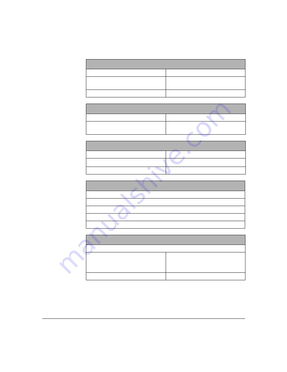
Audio and Video Inputs

Audio Input

1 Line in RCA Phono

Video Input

1 Composite RCA Phono, PAL or 
NTSC

Peripheral camera port

MiniDin-8

Audio and Video Outputs

Audio Output

1 Line out RCA Phono

Video Output

1 Composite RCA Phono PAL or 
NTSC 

Internal Camera

Image sensor

1/3” Color

Lens

f1.6

Manual Tilt

+25º / -2º

Full Duplex Audio Processing

Handset or Handsfree Speakerphone Modes
Adaptive Sub-band Echo Cancellation
Automatic Gain Control
Internal Speaker
Internal Microphone

External  PTZ Camera Control

3 Serial Data RS-232/V2.4 1.2 to 115.2kbps
Connector

9 way D-type Female, DCE
8 pin Mini-DIN Female, custom 
pinning.

PTZ  Drivers Supported

Canon VCC4, Sony EVI-D100

Summary of Contents for mm146

Page 1: ...ACU800A PSTN mm146 IP Videophone mm156 IP PSTN Videophone User Guide...

Page 2: ...of this manual Check the Black Box web site for relevant information If you still have a problem contact Black Box Technical Support If this is not possible contact Customer Services UK and Internatio...

Page 3: ...specification to ensure compatibility Do not use the videophone if you suspect a gas leak Operation of any electrical equipment can generate sparks which may ignite the gas and cause an explosion Do...

Page 4: ...roduct must only be used with the provided power supply This power supply has been extensively tested for use with the product use of an alternative power unit may invalidate any international type ap...

Page 5: ...g Started This guide describes all the features of the mm146 and mm156 videophones and is written both for administrators who are responsible for installing and configuring the videophone and those wh...

Page 6: ...over a regular telephone line 2 Make video calls over a regular telephone line Unique technology mm146 and mm156 videophones offer a range of unique features that improve the user and administrator e...

Page 7: ...r flexibility when in a call These include 1 Full duplex Acoustic Echo Canceller for pause free hands free audio confer ences with no clipping 2 Digital zoom 3 Image control faster sharper 4 Local and...

Page 8: ...t may operate over either the PSTN or an IP network Unpacking Your shipment should contain the following components Videophone unit and handset Power supply and mains lead Standard network cable RJ 45...

Page 9: ...cable into the handset then connect the other end into the socket on the base of your videophone 2 Press the handset cable into the channel on the base of the unit To connect the PSTN line cable mm156...

Page 10: ...a standard straight pinned Cat 5 Connecting the Power Supply To connect the power supply 1 Connect the power supply adapter to the circular power jack labeled 12 VDC 3A on the back of your videophone...

Page 11: ...ilt in camera on your videophone to ensure that the video image you send is crisp and clear To focus the camera 1 Press the menu button to display the Setup Menu options 2 Press the number 3 key to vi...

Page 12: ...rame rate of the video you are sending to adjust the balance between smoothness and clarity See Images on page 33 for more information If movement is important set the Video Mode to Motion if clarity...

Page 13: ...ou are setting up the mm146 or mm156 you should follow the steps in this chapter and then go on to the next chapter which explains how to make calls Setup Menus The videophone is configured using the...

Page 14: ...e way in which you navigate through the menus change settings and save your changes is the same in each case Highlighting a field Use the Up and Down arrow keys on the key pad to move the cursor to th...

Page 15: ...Setup on page 17 Camera Video Setup Displays the Camera Video Setup menu in which you set up video presets and remote access See Setting Camera Video Presets on page 40 Image Options Displays the Imag...

Page 16: ...e Right and Left arrow keys to scroll through the pages of contacts and view all entries in your Phone Book Press a number key on the key pad to make a call to the desired contact Entering Contacts in...

Page 17: ...ither IP 48 32K IP 64 32K IP 96 32K IP 128 32K IP 160 32K Choose PING to test the network path to another device 5 Highlight the Addr field and enter the IP address or telephone number of the party yo...

Page 18: ...same network can then be updated with Phone Book entries contained in the Master unit In this way multiple Slave units on your LAN can easily be updated with the Phone Book from a single Master unit...

Page 19: ...k To check your updated Phone Book on a Slave unit 1 Press the exit button twice then press the start button 2 The Speed Dial list displays with the imported Phone Book entries from the Master Phone b...

Page 20: ...ct ON to activate Auto Dialer Select OFF to turn the auto dialer off Intercom Dial The Intercom feature allows you to dial the last part of the IP address of other IP videophoness within your network...

Page 21: ...Use the Left or Right arrow keys to scroll through the country code options Call Waiting You may need to disable the Call Waiting feature on your videophone to prevent the disruption of video calls En...

Page 22: ...ol Protocol is enabled when the address allocation is done automatically When DHCP is enabled the IP Address Net Mask and Gateway options are greyed out as these parameters are setup automatically To...

Page 23: ...sent a period in the IP address Net Mask Change the Net Mask to a valid subnet mask for your network for example 255 255 255 0 Use the number keys on the key pad use the key located at the bottom left...

Page 24: ...ax Data Speed Select the Max Data Speed using the Right or Left arrow keys on your key pad The Max Data Speed feature is for limiting the bandwidth used for incoming calls This allows you to force all...

Page 25: ...pient s videophone The port number is separated from the IP address by a colon entered using the right arrow key The UDP port number can be configured for two purposes 3 To allow incoming calls to be...

Page 26: ...or part of one such as your extension number Ths number is allocated by your system administrator The format follows the E164 standard and the length is user defined Gatekeeper Mode Options are ON AUT...

Page 27: ...l if using a document camera where text is displayed in the image Select MIRROR to display the self view as a mirrored image more comfortable for talking head operation Video Mode Allows you to custom...

Page 28: ...viewed on your TV Use the Right or Left arrow keys to select FULL or MEDIUM Select FULL for full screen size Select MEDIUM for smaller than full screen size This may be desirable for some application...

Page 29: ...by pressing the speaker button Manually call other IP videophones using an IP address alias or E 164 number by pressing the start button twice Use the Speed Dial menu to make any type of call by pres...

Page 30: ...ill ring a call when a menu is displayed Exit to the idle screen to answer To convert the call to a video call 1 The receiving party presses the Start Dial button While the video is connect ing a mess...

Page 31: ...f the person you are calling 2 The person you are calling needs to press the start button to answer unless they have set the Intercom Answer feature to Auto Setting Intercom Answer The Intercom Answer...

Page 32: ...at the bottom left of the key pad or enter a space using the Right arrow key to represent a period in the IP address 4 Alternatively instead of entering the IP address you can enter the name in the N...

Page 33: ...make a speed dialed call 1 Press the start button The Speed Dial Menu appears showing the names of up to nine contacts already set up on page 1 typical screen shown Use the Right and Left arrow keys t...

Page 34: ...ber 4 key to display the Dialed Calls List below 3 Use the Right or Left arrow keys to select scroll through the list of Dialed numbers The name address speed of connection and call duration or status...

Page 35: ...en The numbers can be saved or dialed as for Dialed calls To access the Missed Calls List 1 Press the menu button then press the number 1 to display the Phonebook 2 Press the number 6 key to display t...

Page 36: ...34...

Page 37: ...ing the Auto Answer feature Receiving a Call If your videophone is called by a remote user and Auto Answer is set to OFF the following screen is displayed Pick up the handset or Press the start button...

Page 38: ...press the number 2 key to display the Communications Setup menu 2 Press the number 2 key access network setup and the 7 key to highlight the Auto Answer option 3 Use the Right or Left arrow keys to se...

Page 39: ...ring a Call This chapter explains how to use the following function buttons on your videophone during a call Volume Picture in Picture Privacy Snapshot Source Image These buttons are accessed from the...

Page 40: ...incoming calls A green status bar is displayed on the screen indicating the volume level Picture in Picture Picture in Picture PiP presents a mirrored self view image or the image from an external cam...

Page 41: ...mage Press the snapshot button during a call when you need to view a still shot of for example an object at the remote end When you press the snapshot button a small camera icon appears in the upper r...

Page 42: ...ion allows you to control the camera s at the far end if remote access is enabled at the far end To engage camera control at the near end Press the source button a second time to engage control at the...

Page 43: ...not fit on the screen Use the buttons Change the resolution of SENT video You may need to drop to low resolution during a call if you run out of bandwidth and the speech becomes distorted Or during a...

Page 44: ...42...

Page 45: ...our videophone including TV set Second camera Pan Tilt Zoom camera Document cameras Video recorder VCR PC Warning Before connecting any equipment that was not supplied with your videophone you must en...

Page 46: ...ort 1 For RS 232 serial peripherals and PTZ cameras DB9 female DCE pinning requires a straight pinned DB9 cable for connection to a PC Port 2 Camera For RS 232 serial periperals and external cameras m...

Page 47: ...h phono audio and video A V inputs or a SCART to phono adaptor 1 Connect one end of the standard A V cable to Audio In on your TV and connect the other end to Audio Out on your videophone 2 Connect on...

Page 48: ...ophone 2 If the camera has a built in microphone that you want to use connect the camera s audio output to your videophone s Audio In 3 Press the menu button to access the Setup Menu 4 Press the numbe...

Page 49: ...far end can switch between these video sources and select the video they want to view during the call To switch between video sources during a call 1 Press the source button once for far end control o...

Page 50: ...tton then press the number 3 key to display the Camera Video Setup menu 2 Press the number 1 key Preview Set Preset After a pause the screen displays showing your image taken by the internal camera To...

Page 51: ...s the number you have assigned to the preset the top right of the screen shows the source 4 To set further presets repeat steps 1 to 3 as many times as necessary You can define up to nine presets 5 Pr...

Page 52: ...Viewing Video Presets To view near end presets when not in a call 1 Press the menu button then press the number 3 key to display the Camera Video Setup menu 2 Press the number 1 key to display Previe...

Page 53: ...play pre recorded video clips including the soundtrack during a video call To connect a VCR to your videophone You need a pair of phono A V cables 1 Connect one end of the phono A V cable to Audio In...

Page 54: ...the VCR to start playing the clip The person at the far end sees and hears the video clip When the clip has finished Press Stop on the VCR Additional Information Information about connecting peripher...

Page 55: ...scriptive text at the bottom of the remote screen during a call You can enable it for incoming calls in the User Options Menu See Setting up the User Options on page 12 Using a Security PIN The securi...

Page 56: ...r OFF If the PIN mode is ON the calling party must enter the Supervisor PIN to change the video presets from a remote location during the call Note If you are a calling a unit that has both the Securi...

Page 57: ...initiation ID Display Allows you to control whether the ID of the remote user is displayed on your TV screen Select ON to display the remote user s ID for the first 8 seconds of the call Select HOLD t...

Page 58: ...Use the Down arrow key to highlight the PIN field Use the number keys to enter the four digit Supervisor PIN 4 Press the start button to dial your call 5 When the call is connected press the source k...

Page 59: ...ing from pan tilt zoom PTZ cameras PC to PC data transfer external third party peripheral control or for telemetry data transmission during a video call Notes 1 The serial connection does not interfer...

Page 60: ...such as HyperTerminal Select to disable the port Baud Rate Set the Baud Rate using the Right or Left arrow keys This field determines the data rate at which the data port operates and varies accordin...

Page 61: ...ts the Baud Rate for Data Port 2 Handshaking This item sets the handshaking for data port 2 The operation is as detailed for data port 1 Data Port 3 This item sets the mode for Data Port 3 Accessory T...

Page 62: ...60...

Page 63: ...pport page at the front of this User Guide for the relevant Customer Service information for your location The software version of your videophone You will need to quote the software version if you co...

Page 64: ...ll Report The following fields are displayed 3 Press the exit button to return to the Diagnostics menu Call Time The length of the call Speed The speed of information transfer in bytes per second Prot...

Page 65: ...isplayed 2 Press exit button to return to the Setup Menu Total Packets An accumulated count of all network packets IP Packets An accumulated count of IP packets Other Packets An accumulated count of o...

Page 66: ...64...

Page 67: ...encountered with the operation of the unit and follow any relevant advice for solving your problem Carefully check the power and wiring for all external cameras used in the system and any other periph...

Page 68: ...f the light is off When making calls the unit reports Dialing but does not connect There is no route to the other device or the firewall may be blocking the transmission path betrween devices Check th...

Page 69: ...n for the mm146 and mm156 videophones ITU Recommendations Supported ITU T H 324 H 323 Video H 263 H 261 Audio G 723 G 711 G 722 Control Protocol H 245 Video Resolution CIF 352 x 288 pixels 15 fps QCIF...

Page 70: ...AL or NTSC Internal Camera Image sensor 1 3 Color Lens f1 6 Manual Tilt 25 2 Full Duplex Audio Processing Handset or Handsfree Speakerphone Modes Adaptive Sub band Echo Cancellation Automatic Gain Con...

Page 71: ...ze Input Auto Connect Persistent Dial Sequential List Digital Pan Tilt Zoom 3x zoom On screen Diagnostics Call Duration Quality Downloadable Software Updates Via IP Network or RS 232 Interface Network...

Page 72: ...x 9 85 D 180mm H x 210mm W x 250mm D Weight 1 2 kg Environmental Operating Temperature 0 to 40 C Non operating Temperature 40 to 70 C Humidity 5 to 95 Packing Individual Corrugated Carton 19 5 H x 10...

Page 73: ...r There are no user serviceable parts inside and exposing the interior places the user at risk of serious electric shock If you suspect a fault contact your supplier for a new adapter Should the power...

Page 74: ...ctor of the mm146 Safe to touch by the user POWER connector SELV Safety Extra Low Voltage For connection of the power supply unit Safe to touch by the user AUDIO and VIDEO connectors SELV Safety Extra...

Page 75: ...num rique de la classe B est conforme la norme NMB 003 du Canada FCC Part 15 USA This equipment has been tested and found to comply with the limits for a Class B digital device pursuant to Part 15 of...

Page 76: ...h the FCC if you believe it is necessary The telephone company may make changes in its facilities equipment operations or procedures that could affect the operation of the equipment If this happens th...

Page 77: ...ity video transmission without the long distance expense of a regular ISDN call Basic Network Configuration The videophone supports a 10 or 100 Base T connection over IP based networks using static an...

Page 78: ...ernet based video conferencing equipment What devices will you make calls to Do you need to make calls to H 320 equipment yes yes Internet Private Line yes no no H 323 Packet Buddy no yes no Example 1...

Page 79: ...68 1 254 IP Address 192 168 2 2 Subnet Mask 255 255 255 0 Default Gateway 192 168 2 254 192 168 1 254 IP Address 192 168 1 1 Subnet Mask 255 255 255 0 Default Gateway 192 168 1 254 192 168 2 254 Hub S...

Page 80: ...k 255 255 255 0 Default Gateway 192 168 2 254 UDP port 5000 192 168 2 254 Hub Switch Firewall Router Internet Router Firewall Hub Switch Notes Callers dial the external IP address of the firewall appe...

Page 81: ...4 99 88 77 66 99 88 77 67 IP Address 192 168 2 1 Subnet Mask 255 255 255 0 Default Gateway 192 168 2 254 192 168 2 254 Hub Switch Firewall Router Internet Router Firewall Hub Switch Notes An external...

Page 82: ...Default Gateway 192 168 2 254 192 168 2 254 Hub Switch Gateway Router ISDN Router Firewall Hub Switch Notes An external IP address and UDP port setting of 5000 is required for each videophone You may...

Page 83: ...ng the videophone handset 7 network cable 8 power supply 8 D Data options menu 57 Data port 1 58 Data port 2 59 Data ports 57 Data speed 22 Default presets 47 DHCP 20 Diagnostic information 61 Dialed...

Page 84: ...iving a call 35 Remote access 54 Remote camera access 40 Remote control of cameras 49 Requirements 6 Resolution 41 S Screen size 41 Security PIN 51 Selecting menu options 12 Self view 38 Setting defau...

Page 85: ...4 18 21 64 78 Unpacking the videophone 6 Updating slave units 16 User ID 53 User options 53 User options menu 51 53 55 V VCR 49 Video mode 10 25 Video presets 47 setting up 47 viewing 49 Volume 38 Vol...

Reviews: