background image

13

KT-100-3

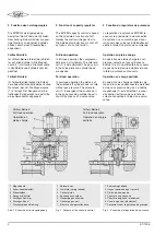
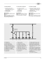
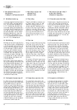
4.3 Schematic wiring diagram

• part winding start (PW)

- analogous for direct on line and

star-delta start

• start unloading
• capacity control

Attention!
Danger of refrigerant migration!
Switch off the capacity control
during compressor standstill!

!

!

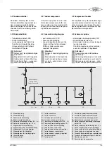
4.3 Schéma de principe

• démarrage à bobinage partiel (PW)

- analogue pour démarrage direct et

pour démarrage à étoile-triangle

• démarrage à vide
• régulation de puissance

Attention !
Danger de déplacement du fluide
frigorigène !
Déclencer le régulateur de puissan-
ce pendant l'arrêt du compresseur !

!

!

4.3 Prinzipschaltbild

• Teilwicklungs-Anlauf (PW)

- gilt sinngemäß auch für Direkt-

und Stern-Dreieck-Anlauf

• Anlaufentlastung
• Leistungsregelung

Achtung!
Gefahr von Kältemittel-Verlage-
rung!
Leistungsregler während des
Verdichter-Stillstands nicht mit
Spannung beaufschlagen!

!

!

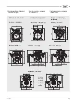
N

L 1

0 1

S i c h e r h e i t s k e t t e

S a f e t y   c h a i n

C h a î n e   d e   s é c u r i t é

K 1

K 1 T

Y 1

K 2

Y 2

Y 3

K 1

K 1 T

K 2

K 1

B 2

K 1

B 1

S 1

K 1

R 8

P W 1

P W 2

0 , 5   . .   1   s e c

C R

F 1

F 3

F1 Steuersicherung
F3 Steuersicherung

K1 Schütz erste Teilwicklung
K2 Schütz zweite Teilwicklung
K1T Zeitrelais Teilwicklungs-Anlauf (0,5 .. 1 s)
Y1 Magnetventil für Anlaufentlastung
Y2 Magnetventil in der Flüssigkeitsleitung
Y3 Magnetventil für Leistungsregler
B1 Steuerelement für Verdichter
B2 Steuerelement für Leistungsregler
R8 Ölsumpfheizung
S1 Steuerschalter

F1 Control circuit fuse
F3 Control circuit fuse

K1 Contactor first part winding
K2 Contactor second part winding
K1T Time relay part winding start (0.5 .. 1 s)
Y1 Solenoid valve for start unloading
Y2 Solenoid valve in liquid line
Y3 Solenoid valve for capacity regulator
B1 Control device for compressor
B2 Control device for capacity regulator
R8 Crankcase heater
S1 Control switch

F1 Fusible de protection de commande
F3 Fusible de protection de commande

K1 Contacteur premier bobinage partiel
K2 Contacteur second bobinage partiel
K1T Relais temporisé démarrage à bobinage

partiel (0,5 .. 1 s)

Y1 Vanne magn. pour démarrage à vide
Y2 Vanne magn. dans la conduite de liquide
Y3 Vanne magn. pour régulateur de puiss.
B1 Dispositif de commande pour compresseur
B2 Dispositif de commande pour régulateur

de puissance

R8 Résistance de carter
S1 Commutateur de commande

Summary of Contents for KT-100-3

Page 1: ...r de puissance 4 3 Limites d application avec op ration en charge partielle 5 4 Commande de compresseurs r gulation de puissance 12 5 D marrage vide par r gulation de puissance 14 6 Dimensionnement de...

Page 2: ...insi que les tandems concern s sont disponibles avec un r gulateur de puissance Il est livr soit compl tement mont en usine soit comme set de montage pour installation ult rieure sur place Montage ult...

Page 3: ...iligen Teillast Verhalten der Einzelver dichter siehe Abb 1a Fig 1b Average factors for power con sumption with tandem compres sors The part load behaviour of symme trically controlled tandem compres...

Page 4: ...liment e Le canal d aspiration est ferm dans la t te de culasse concern e l aide d une servo vanne 2 Funktion des Leistungsreglers Die BlTZER Leistungsregelung basiert auf dem Prinzip der Zylinder Abs...

Page 5: ...al losses Therefore the application ranges of the capacity controlled compressors are to some extent restricted Application limits always refer to the nominal voltage of the compressor are also valid...

Page 6: ...idissement additionnel temp rature de gaz aspir limit e Surchauffe l aspiration 10 K Einsatzgrenzen R134a Legende Restleistung to Verdampfungstemperatur C toh Sauggastemperatur C tohSauggas berhitzung...

Page 7: ...C 10 Motor 1 Motor 2 toh 20 C 60 50 40 30 20 tc C 50 40 30 20 10 to C 10 Motor 1 Motor 2 toh 20 C toh 20 K 50 4FC 3 2Y 4CC 9 2Y 50 4VC S 6 2Y 4G 30 2Y 60 50 40 30 20 tc C 50 40 30 20 10 to C 10 toh 2...

Page 8: ...n 10 K Einsatzgrenzen R407C Legende Restleistung to Verdampfungstemperatur C toh Sauggastemperatur C tohSauggas berhitzung tc Verfl ssigungstemperatur C Zusatzk hlung toh 20 C Zusatzk hlung oder max 0...

Page 9: ...2 4CC 9 2 sont valable seulement pour VARICOOL refroidissement par gaz aspir SL A KT 100 3 70 60 50 40 30 20 10 tc C 30 20 10 0 20 to C Motor 1 Motor 2 toh 20 C toh 10 K 70 60 50 40 30 20 10 tc C 30 2...

Page 10: ...e eingeschr nkt Einsatzgrenzen KT 100 3 4T 2 Y 4P 2 Y 4N 2 Y 4H 2 Y 4G 2 Y R134a R12 30 40 50 60 70 30 40 50 30 40 50 30 25 20 15 10 23 18 12 38 33 27 30 30 30 27 22 40 29 20 45 45 40 R22 R404A R507A...

Page 11: ...ream must be controlled in such a way that a suf ficient cooling of the compressor is always guaranteed Water cooled cylinder heads For 4Z 5 2 Y 4N 20 2 Y 4J 13 2 Y 6F 50 2 Y and all open compressors...

Page 12: ...ajust dans une fa on que le fonctionnement pendu laire doit tre vit Une variation de charge cause une variation assez rapide de la pres sion d aspiration A cause de la capacit d accumulation de l vap...

Page 13: ...herung F3 Steuersicherung K1 Sch tz erste Teilwicklung K2 Sch tz zweite Teilwicklung K1T Zeitrelais Teilwicklungs Anlauf 0 5 1 s Y1 Magnetventil f r Anlaufentlastung Y2 Magnetventil in der Fl ssigkeit...

Page 14: ...function can also be archieved by the capacity control in conjunction with a pre unloading of the discharge side Necessary additional parts 1 check valve Mount into the discharge line Rate it for to...

Page 15: ...Achtung Gefahr von Fl ssigkeitsschl gen beim Start Magnetventil in der Fl ssigkeits leitung darf erst beim Start des Verdichters ffnen ausgenom men bei Abpumpschaltung N L 1 0 1 S i c h e r h e i t s...

Page 16: ...demand e Pour des installations plusieurs vapo rateurs ou sections d vaporateurs obtu rables I aide des vannes magn tiques il ne faut r unir les conduites d aspiration sur un collecteur commun qu on...

Page 17: ...ccessibles 3 0 3 3 6 6 3 5 3 3 0 4 4 3 9 4 5 8 4 5 3 4 2 0 4 0 8 537 506 149 149 237 237 4 1 7 4 7 8 3 8 2 4 5 3 308 226 226 309 276 445 365 309 226 226 445 484 308 4FC 3 2 Y 4CC 9 2 Y 6J 22 2 Y 6G 40...

Page 18: ...2 Y 4G 2 Y W4HA W4GA beide Zylinderb nke m glich both cylinder banks possible possible sur n importe laquelle des deux culasses 6J 22 2 Y 6G 40 2 Y 6H 2 Y 6G 2 Y W6HA W6GA u ere Zylinderb nke outer cy...

Page 19: ...277 Coil 281 Valve 283 Electric connector of the device Parts which are not numbered are included in the kit of higher ranking 8 Montage ult rieur Le montage d une r gulation de puissance peut n cess...

Page 20: ...ten Subject to change Toutes modifications r serv es 08 07 80300101 Bitzer K hlmaschinenbau GmbH Eschenbr nnlestra e 15 71065 Sindelfingen Germany tel 49 0 70 31 932 0 fax 49 0 70 31 932 0 www bitzer...

Reviews: