7
+380 44 507 02 07
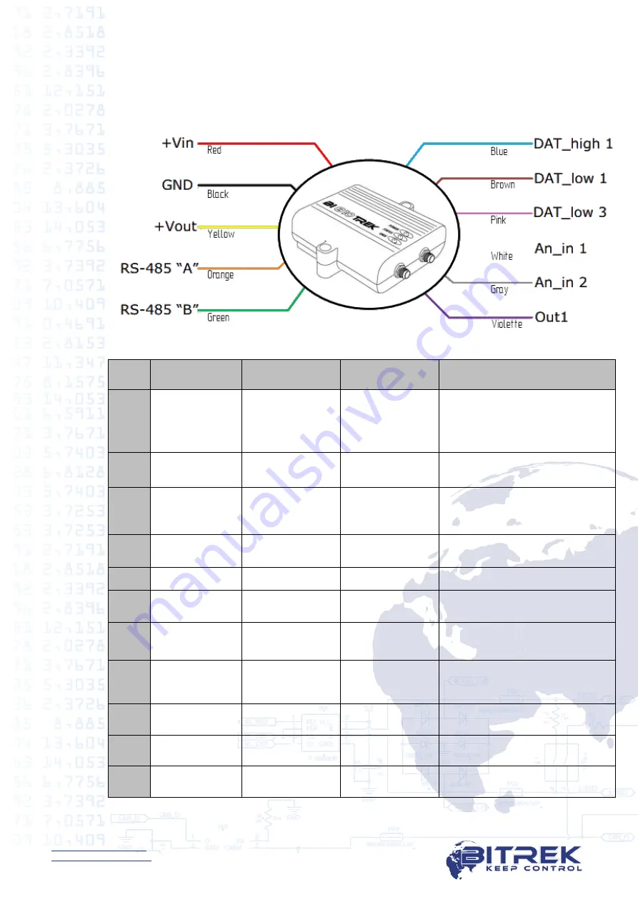
Connection of the Power Supply, Discrete and Analog Sensors,
as well as Extra Devices
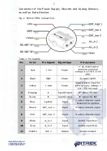
Fig. 2. BI-810 TREK Contact Pins
Table 2. Pin legends
No.
Color
Pin legend
Signal type
Pin purpose
1
Red
+ Vin
Power
"+" on-board power
terminal (nominal
voltage is 12 VDC or 24
VDC)
2
Black
GND
Power
Ground (earth)
3
Yellow
+ Vout
Power
Secure power input for
extra sensors. V
Vin (350 mA max)
4
Oragnge
A
Input/Output
"A" signal RS-485
5
Green
B
Input/Output
"B" signal RS-485
6
Blue
Ignition
Input
1-active discrete input
Reserved for ignition
7
Brown
DAT_low 1
Input
0-active discrete input
8
Pink
DAT_low 3
Input
0-active discrete input
9
White
A_in 1
Input
Analog input No.1
10
Gray
A_in 2
Input
Analog input No.2
11
Violette
Out 1
Output
Discrete output


