background image

- 17 -

USE

USEFUL ADVICE

advised to have the following checks car-
ried out: 

condensing heat exchanger

• 

burner;

• 

exhaust fume duct and fl ue;

• 

pressurisation of the expansion tank;

• 

fi lling up of the central heating circuit;

• 

bleeding of air from the central heating 

• 

system;
general check of the appliance’s opera-

• 

tion.

External cleaning

3.5 

Before carrying out any clean-
ing, disconnect the appliance 
from the electrical mains, using 
the fused spur isolation switch 
fi tted adjacent to the appliance.

To clean the external panels, use a cloth 
soaked in soapy water. Do not use solvents, 
abrasive powders or sponges. 

Do not 

carry out cleaning of the appliance 

and/or its parts with readily fl ammable sub-
stances (for example petrol, alcohols, naph-
tha, etc.).

Operational faults

3.6 

If the boiler does not function and a code 
that alternates between the letter 

Er

 and the 

writing 

reset

 (


see "LCD general features" to 

page 10


) appear on the LCD display, it indi-

cates that the safety lock-out has stopped 
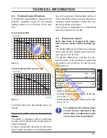
the boiler. The display background fl ashes 
( Fig. 3.3 ).


Fig. 3.3

RESET

RESET

For the fi rst lighting up and following main-
tenance procedures for the gas supply, it 
may be necessary to repeat the resetting 
operation several times so as to remove the 
air present in the pipe work.
Safety lock-out may occur even in case of a 
blockage of the condensate drainage (e.g. 
plugged drain pipe). It is advisable to check 
the condensate drainage pipe and traps for 
cleanness.
Press the reset key on the boiler control 
panel  11  ( Fig. 3.1 ) to reset its functioning.

In this case and in case of per-
sistent lock-out call a competent 
and responsible Service Engi-
neer.

Other operational faults signalled on the 
LCD display

If the LCD display displays a code that al-
ternates between the letter 

Er

 and the 


symbol, the boiler has an anomaly that can-
not be reset.
The display background fl ashes ( Fig. 3.4 ).

Summary of Contents for Activ A 18S

Page 1: ...n instructions ActivA Models G C Appl No Activ A 18S 41 583 11 Activ A 25S 41 583 12 Activ A 30S 41 583 13 U n i t 3 A T h o r n t o n R o a d I n d E s t a t e O f f H o c k n e y R o a d B r a d f o...

Page 2: ...observed to pre vent accidents of mechanical or generic origin e g injuries or bruises DANGER The indications marked with this symbol must be observed to pre vent accidents of electric origin electroc...

Page 3: ...boiler is fitted with all the safety and control devices required by the current Regulations Ensure that check with the Installer that he has connected and terminated the pressure relief valve in a ma...

Page 4: ...quite normal that the boiler produces a white plume of conden sation vapour from the flue terminal This is due to the high efficiency of the appliance and may be particularly evident with low outdoor...

Page 5: ...o not extinguish with water Precautions Do not incinerate Avoid contact with broken leaking phials Do not purposely puncture First aid medical attention must be sought following eyes skin contact wash...

Page 6: ...on of an external control you can eliminate the boiler from your fault analysis If the boiler is fitted with a digital programmer when setting the times for automatic opera tion remember that for ever...

Page 7: ...the boiler 53 7 7 Checking the gas supply pressure 54 7 8 Checking the inlet pressure 54 7 9 Enabling functioning of the external temperature probe by the remote control 55 7 10 Setting the K coeffici...

Page 8: ...2 3 4 5 6 7 8 9 10 Fig 1 2 Gas supply label 3 C h circuit pressure gauge 4 C h flow valve 5 Gas inlet valve 6 C h return valve 7 Condensate drain pipe 8 Main circuit drain valve 9 C h pressure relief...

Page 9: ...LCD display 14 RESET that takes all parameters back to the factory value occurs only by setting parameter 08 04 Reset is displayed by switch on of all symbols present on the dis play U n i t 3 A T h o...

Page 10: ...10 Flue probe intervention lockout Er 11 Flame detection error LCD FUNCTION Er 14 Faulty pump or primary temperature above 105 C Er 04 Faulty primary circuit no water or absence of flow Er 05 Faulty...

Page 11: ...d burner ignition for setting the system uu flashing tempera ture flashing Boiler in chimney sweep functioning mode The chimney sweep is activated by setting parameter 09 01 and is visualised by the s...

Page 12: ...that shown in Fig 2 2 If the pressure reading on the pressure gauge is below that shown in Fig 2 2 then the system will require topping up A filling loop is normally provided by the Installer for thi...

Page 13: ...ed in the lower part of the boiler are open Fig 2 3 Fig 2 3 Open position Turn on the electricity supply to the boil er switching on the fused spur isolation switch The LCD display displays the state...

Page 14: ...t in c h power When the boiler has a power request in the c h mode the symbol is displayed on the display followed by an increase of the c h water flow temperature The symbol flashes Fig 2 8 Fig 2 8 C...

Page 15: ...tch Shut off the gas supply cock and the valves for the water circuits fitted under the boiler Fig 2 11 Fig 2 11 Close position If necessary empty the hydraulic circuits see section Emptying the c h s...

Page 16: ...th consequent risk of freezing do not switch off the boiler at the fused spur isolation switch or close the gas inlet cock If the boiler is deactivated have a qualified technician empty the boiler the...

Page 17: ...LCD display it indi cates that the safety lock out has stopped the boiler The display background flashes Fig 3 3 Fig 3 3 RESET RESET For the first lighting up and following main tenance procedures for...

Page 18: ...relief valve to open So that this does not happen and to decrease the pressure to a normal value it is advisable to vent some of the water in the appliance through the bleed valves present in the radi...

Page 19: ...l lockout 03E Faulty primary circuit no water or absence ol fow 04E Faulty fan control system 05E Faulty c h temp probe NTC 06E Faulty external temp probe NTC 08E Faulty flue temp probe NTC 09E Flue p...

Page 20: ...verview 4 1 Fig 4 1 15 18 34 32 28 22 19 35 27 23 25 26 16 31 21 24 29 33 17 30 20 36 37 U n i t 3 A T h o r n t o n R o a d I n d E s t a t e O f f H o c k n e y R o a d B r a d f o r d B D 8 9 H Q 0...

Page 21: ...sing heat exchanger 17 Safety thermostat 18 Flame detecting electrode 19 Air manifold 20 C h pressure relief valve 21 Automatic airpurger valve 22 Pump 23 Pump vent plug 24 Gas valve 25 36 37 38 17 33...

Page 22: ...inal block Primary circuit pressure switch 28 Condensate trap 29 Fan 30 31 Air box air gas mixer Ignition electrode 32 Burner 33 C H expansion tank 34 By pass valve 35 Flue outlet pipe 36 Air intake p...

Page 23: ...ements valves by pass ensures a minimum water circulation inside the con densing primary exchanger The by pass is calibrated to a differential pressure of about 0 3 0 4 bar Expansion vessel 4 4 Note t...

Page 24: ...ffiency G31 c band A 91 3 to the minimum useful output A referred to the net calorific value at 15 C and 1013 25 mbar G20 34 02 MJ m3 G31 46 34 MJ kg B referred to the gross calorific value at 15 C an...

Page 25: ...gas figures Nominal heat input A E kW 18 0 CO2 content with gas G20 9 3 9 9 O2 content with gas G20 3 8 CO content with gas G20 ppm 120 Exhaust temperature E C 63 NOx class 5 Weighted NOx ppm 20 E Va...

Page 26: ...ffiency G31 c band A 91 2 to the minimum useful output A referred to the net calorific value at 15 C and 1013 25 mbar G20 34 02 MJ m3 G31 46 34 MJ kg B referred to the gross calorific value at 15 C an...

Page 27: ...s figures Nominal heat input A E kW 25 0 CO2 content with gas G20 9 2 9 8 O2 content with gas G20 3 8 CO content with gas G20 ppm 160 Exhaust temperature E C 75 NOx class 5 Weighted NOx ppm 25 E Value...

Page 28: ...effiency G31 c band A 91 2 to the minimum useful output A referred to the net calorific value at 15 C and 1013 25 mbar G20 34 02 MJ m3 G31 46 34 MJ kg B referred to the gross calorific value at 15 C...

Page 29: ...as figures Nominal heat input A E kW 30 0 CO2 content with gas G20 9 2 9 8 O2 content with gas G20 3 8 CO content with gas G20 ppm 153 Exhaust temperature E C 80 NOx class 5 Weighted NOx ppm 27 E Valu...

Page 30: ...ions and reference should be made to the current ETCI rules for electrical installations Location of appliance 5 2 The appliance may be installed in any room or internal space although particular atte...

Page 31: ...O M Vertically from a terminal in the same wall 1500 N Horizontally from a terminal in the same wall 300 O Above the roof pitch with roof slope less than or equal to 30 350 O Above the roof pitch with...

Page 32: ...iler includes a trap 21 on page 20 that prevents the combustion products en tering the drain The boilers incorporate a condensate trap with a 75mm seal to comply with BS6798 2000 The schematic diagram...

Page 33: ...s valve which protects the main heat exchanger in case of reduced or interrupted water circulation through the heating system due to the closing of thermostatic valves or cock type valves within the s...

Page 34: ...ed Details on flushing procedure are given in the section Initial filling of the system to page 51 of this manual Electrical supply 5 10 Warning this appliance must be earthed External wiring to the a...

Page 35: ...fety relief valve and the condensate drain must be connected to a suitable drain or discharge in a safe manner The electrical wiring must conform with cur rent Regulations in particular the boiler mus...

Page 36: ...system but also has an anti corrosive effect by promoting formation of a protective skin on metal surfaces and neu tralising gases present in the water We recommend the use of a suitable uni versal i...

Page 37: ...plastic sizes in mm o d Condensate drain to be realised with min pipe 30 mm Mounting the boiler 6 6 Assemble the pre piping kit bracket by screwing the four screws J Fig 6 3 Fix the c h valves L and t...

Page 38: ...he pre selected kit The horizontal routes of the flue pipes must incline about 1 5 degrees 25 mm per me ter therefore the terminal must be higher than the intake at the boiler The single coaxial pipe...

Page 39: ...13 C33 C53 C63 Refer to the sheet provided with the pre selected kit in separate packaging The horizontal routes of the flue pipes must incline about 1 5 degrees 25 mm per me ter The terminal must be...

Page 40: ...zontal and however the terminal must al ways exhaust horizontally Additional bends at 45 or 90 Fig 6 8 C Coaxial bends 60 100 mm These bends when used with the pipe re duce the maximum length of the...

Page 41: ...ndensation products During the pipes dimensioning phase take into consideration the static pressure resi due of the fan Useful static pressure at nominal heat input Activ A 18S 120 Pa Activ A 25S 180...

Page 42: ...v A 25S and 9 metres for Activ A 30S can be achieved utilising extensions Each additional elbow reduces the overall acceptable length of the flue system as fol lows 45 60 100 mm reduce length by 0 5 m...

Page 43: ...en to an effective earth plant The earth cable must be the longest of the electric power supply cables The appliance s electric power supply cable or wire must have a section no less than 0 75 mm2 it...

Page 44: ...at The electric cables of the ambient thermo stat are inserted between clamps 1 and 3 as in Fig 6 19 or Fig 6 20 or Fig 6 21 Be careful not to connect pow ered cables on clamps 1 and 3 Fig 6 19 1 T Po...

Page 45: ...ered cables on clamps 1 and 3 The route of the boiler and ambient thermo stat s electric power supply cable or wires must follow the route indicated in Fig 6 17 Allow the cables to exit the boiler by...

Page 46: ...provides independent timed and thermostatic control of heating and hot wa ter In Fig 6 25 the boiler is permanently con nected to the main supply The boiler op eration is controlled by the external c...

Page 47: ...r L N 2 3 1 Programmer HTG HW OFF HW ON L N 2 1 4 6 7 10 way junction box Valve colour key WH White GRYE Green Yellow GY Grey OR Orange BU Blue Mid position diverter valve HTG Heating HW ON HotWaterON...

Page 48: ...er thermostat C 1 2 8 7 6 GY WH OR GRYE BU 2 3 8 5 7 MAINS 230V a c Switched 3 Amp fused spur L N 2 3 1 Programmer HTG HW OFF HW ON L N 2 1 4 6 7 10 way junction box Mid position diverter valve HTG He...

Page 49: ...age ones 230 V since they are powered at a safe ty low voltage and their maximum length must not exceed 20 meters Use the clamps indicated in Fig 6 27 to connect the external probe Fig 6 27 Ambient th...

Page 50: ...s of a hydraulic separa tor the secondary circuit s flow rate is put into circulation only when the relative pump is on When the pump of the secondary is off there is no circulation in the correspond...

Page 51: ...ectrical safety shall be carried out by a competent person i e polarity earth con tinuity resistance to earth and short circuit If a fault has occurred on the appliance the fault finding procedure sho...

Page 52: ...g are completed turn on the c h sys tem and run it until the temperature has reached the boiler operating tempera ture The system must then be immedi ately flushed through This procedure must be repea...

Page 53: ...ioned during instal lation The LCD display displays the symbol Fig 7 5 Fig 7 5 Press the 11 key for 2 seconds until symbol appears on the display Fig 7 6 Fig 7 6 11 12 13 14 The LCD display displays t...

Page 54: ...ed adjacent to the appliance Checking the gas supply 7 7 pressure This boiler has been factory tested to the highest quality control standards and set for the minimum and maximum gas work ing pressure...

Page 55: ...Important after the checks all of the test points must be sealed Enabling functioning of the 7 9 external temperature probe by the remote control Functioning with the external probe in the boiler mus...

Page 56: ...mote control optional refer to Fig 7 15 In this case K setting must be done from the remote control External temperature C 20 20 15 10 5 0 5 10 15 20 25 30 40 50 60 70 80 C h flow temperature C K 6 K...

Page 57: ...meter 15 Fig 7 19 is displayed on the LCD dis play Fig 7 19 Using keys 12 or 13 it is possible to change the value of parameter 15 from a minimum of 01 to a maximum of 60 based on the selected bend of...

Page 58: ...he boiler by activating the bipolar switch envisioned during instal lation Press button for more than 3 seconds to enter in Fig 7 21 mode Fig 7 21 0 2 1 8 1 21 15 6 3 9 Press button to display the K R...

Page 59: ...D display Fig 7 26 It is possible to modify parameter 11 by 00 0s to99 600s using keys 12 or 13 each increase or reduction by a unit on the display corresponds to 6 seconds By pressing key 11 Fig 7 23...

Page 60: ...normal on off heating mode the minimum time between two ignitions is set at three minutes re igni tion frequency This time can be changed by a minimum of zero to a maximum of eight and a half min ute...

Page 61: ...Fig 7 31 confirma tion of the inserted value is obtained Press keys 11 and 12 Fig 7 31 at the same time to exit without changing the val ue return to the parameters list Fig 7 33 Press keys 11 12 13 F...

Page 62: ...amming press button Checking the ignition device 7 13 With the burner on high flame close the gas cock After four ignition attempts about four min utes the boiler does not function and a code that alt...

Page 63: ...and temperature controls if fitted Explain how to turn off the appliance for both short and long periods and advise on the precautions necessary to prevent damage should the appliance be inoperative w...

Page 64: ...Activ A 18S Activ A 25S Activ A 30S is displayed on the LCD display Fig 7 44 Fig 7 44 I t is possible to modify parameter using keys 12 or 13 Fig 7 41 Refer to Fig 7 40 and determine the correct Value...

Page 65: ...c h mode Pr 12 C h pump working type Pr 13 Ignition power Pr 14 K value external probe diagram Pr 15 Not used Pr 16 Not used Pr 17 NTC on the c h return Pr 18 Not used Pr 19 Not used Pr 20 PARAMETER D...

Page 66: ...oll the various parameters using keys 12 or 13 until the letters Pr that alternate with code 02 are displayed on the LCD display indicating that parameter 02 has been activated Repeat all the above se...

Page 67: ...estrictor Fig 8 2 refer ring to the Technical Data section page 24 Activ A 18S page 26 Activ A 25S and page 28 Activ A 30S Fig 8 2 Gas restrictor Attention to reassemble repeat the operations carried...

Page 68: ...he inserted value is obtained Press keys 11 and 12 Fig 8 3 at the same time to exit without changing the value re turn to the parameters list Fig 8 5 Press keys 11 12 13 Fig 8 3 at the same time for 1...

Page 69: ...o the appliance and turn off the gas cock before carrying out any procedures whatsoever for cleaning maintenance opening or dismantling boiler panels The Engineer should complete the Service Interval...

Page 70: ...lose the c h isolating valves 5 and 7 in Fig 9 4 Loosen the central heating drain cock 9 indicated in Fig 9 5 Fig 9 5 OPEN CLOSED Main circuit drain valve 9 To make draining easier lift the plug 22 of...

Page 71: ...tor Q by press ing the plastic hook P positioned at the bottom part of the connector Fig 9 8 Unscrew screws N and remove the fan burner unit 33 Fig 9 7 Remove the burner body by pulling to wards the o...

Page 72: ...l an approved Service Engineer Combustion analysis check 9 7 It is recommended that a combustion analy sis check is made Remove the plug as in dicated in Fig 9 9 and carry out combustion analysis chec...

Page 73: ...o exclude some boiler auto matic functions making check and control operations easier Enter in programming mode by pressing keys 11 12 13 Fig 9 11 for 10 seconds at the same time until the letters Pr...

Page 74: ...aximum output Press further key 13 to vary again the output in chimney sweep mode when the LCD display displays the letters DP that al ternate with the heating water temperature value e g 99 the chimn...

Page 75: ...75 NOTES U n i t 3 A T h o r n t o n R o a d I n d E s t a t e O f f H o c k n e y R o a d B r a d f o r d B D 8 9 H Q 0 1 2 7 4 4 8 8 3 8 8 w w w h e a t i n g s p a r e s 2 4 7 c o m...

Page 76: ...U n i t 3 A T h o r n t o n R o a d I n d E s t a t e O f f H o c k n e y R o a d B r a d f o r d B D 8 9 H Q 0 1 2 7 4 4 8 8 3 8 8 w w w h e a t i n g s p a r e s 2 4 7 c o m...

Page 77: ...U n i t 3 A T h o r n t o n R o a d I n d E s t a t e O f f H o c k n e y R o a d B r a d f o r d B D 8 9 H Q 0 1 2 7 4 4 8 8 3 8 8 w w w h e a t i n g s p a r e s 2 4 7 c o m...

Page 78: ...78 NOTES U n i t 3 A T h o r n t o n R o a d I n d E s t a t e O f f H o c k n e y R o a d B r a d f o r d B D 8 9 H Q 0 1 2 7 4 4 8 8 3 8 8 w w w h e a t i n g s p a r e s 2 4 7 c o m...

Page 79: ...U n i t 3 A T h o r n t o n R o a d I n d E s t a t e O f f H o c k n e y R o a d B r a d f o r d B D 8 9 H Q 0 1 2 7 4 4 8 8 3 8 8 w w w h e a t i n g s p a r e s 2 4 7 c o m...

Page 80: ...1 506 1360 Service Tel No 0121 506 1350 Service Fax No 0121 506 1370 www biasi co uk 17962 1848 0 3109 80A5 UK 27 07 2009 N U n i t 3 A T h o r n t o n R o a d I n d E s t a t e O f f H o c k n e y R...

Reviews: