- 38 -
INST
ALLA
TION
INSTALLATION
Fig. 6.3
J
K
L
M
N
L
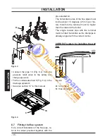
Connect the pipe
• 10
( Fig. 6.4
) from the
pressure relief valve to the safety dis-
charge pipework.
Fit the condensate drain
• 8
( Fig. 6.4 ) in the
drainage pipework.
See also section
• 5.7
in this manual.
Fig. 6.4
10
8
Fitting the fl ue system
6.7
For a correct installation of the fl ue pipe, re-
fer to the sheet provided together with the
pre-selected kit.
The horizontal routes of the fl ue pipes must
incline about 1.5 degrees (25 mm per me-
ter); therefore the terminal must be higher
than the intake at the boiler.
The single coaxial pipe with the terminal
must be fi tted horizontal as the drainpipe is
already angled with the correct incline.
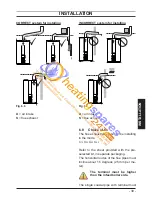
CORRECT system for installing the wall
fl ue
A+S
ASA
Fig. 6.5
A
= air intake
S
= fl ue exhaust


