background image

D12

Nozzles which produce fine droplets are usually recommended for post-emergence 

applications, which require excellent coverage on leaf surfaces. 

The most common nozzles used in agriculture are those which produce medium sized 

droplets. These can be used for contact and systemic herbicide, preemergence surface 

applied herbicide, insecticides and fungicides.

Remember that a spray nozzle in any droplet size category can produce different size 

droplets at different spray pressures. A nozzle might produce medium droplets at low 

pressures, while producing fine droplets as pressure is increased. 

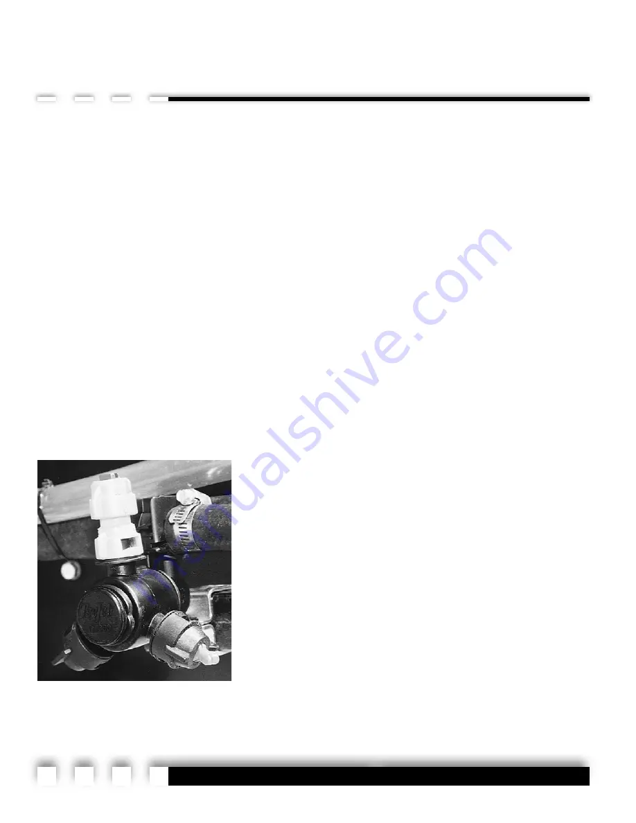
Spray Tip Turret

Each spray nozzle outlet on the Field-Pro IV has been equipped with a 360-degree nozzle 

turret for fast and convenient spray tip changes in the field. With just a twist of your wrist, you can

quickly choose the right tip for the right job, assuming that different types of spray tips have been

installed on each turret. 

You may wish to equip the turret with spray tips for each type of application

you perform, such as burndown, pre-emerge and post applications. Or, you may

want to equip the turret with at least two of the most commonly used tips, so a

quick change can be made in the event a tip gets plugged or damaged.

To change from one tip to another, simply rotate the turret until you hear a

“click”. Because the 360-degree turrets feature 

positive shutoffs between each tip outlet, you can also use the turret to shut off

individual spray tips on the boom. Simply rotate the turret to a “click” position

between spray tip outlets. This feature is particularly useful when you need to

change nozzle spacing or reduce the swath width.

Spray tip turret in 
“off” position.

Summary of Contents for field-pro IV 1600

Page 1: ...West Iowa Street P O Box 394 Hiawatha Kansas 66434 USA Phone 785 742 2949 FAX 785 742 2190 Call Toll Free 1 877 390 4480 www rhs inc com DOM BW013 Revision B OPERATOR S MANUAL Effective May 2006 Last...

Page 2: ...as been carefully designed and ruggedly built to provide many years of dependable service in return for your investment This manual has been prepared to assist you in the operation and maintenance of...

Page 3: ...naging Drift D11 Spray Nozzle Selection D11 Spray Tip Turret D12 Rinsing The Sprayer D13 Maintenance E1 Cleaning E1 Lubrication E2 Grease Fittings E2 Wheel Bearings E2 Line Strainer Maintenance E4 Spr...

Page 4: ...umber plate for the sprayer is located on the right side of the mainframe near the front It is suggested that the serial number be recorded in the space provided in the front of this manual Always pro...

Page 5: ...FETY AND THE SAFETY OF OTHERS FAILURE TO FOLLOW THESE INSTRUCTIONS CAN RESULT IN INJURY OR DEATH THIS SYMBOL MEANS ATTENTION BECOME ALERT YOUR SAFETY IS INVOLVED If you have questions not answered in...

Page 6: ...arded Indicates a potentially hazardous situation that if not avoided could result in death or serious injury and includes hazards that are exposed when guards are removed It may also be used to alert...

Page 7: ...e warranted for ninety 90 days from date of purchase or the remainder of the original equipment warranty period whichever is longer Under no circumstances will it cover any merchandise or components t...

Page 8: ...or exclusions of implied warranties or incidental or consequential damages so the limitations or exclusion in this warranty may not apply This warranty is subject to any existing conditions of supply...

Page 9: ...y weight 8 100 lbs 3674 kg Est Tongue weight 1 350 lbs 526kg empty 4550 lbs 2064 kg full Est Payload 22 200 lbs 10070 kg max Est Boom weight 3 200 lbs 1451 kg SPECIFICATIONS Capacities Sprayer tank 1...

Page 10: ...A9 A B C D E G F P N 67657 A P N DEC HAZ01 A P N 67673 B Safety Sign Locations P N DEC HAZ08 A...

Page 11: ...A10 P N SW001 C P N 67671 C P N DEC HAZ02 D G P N 67672 C P N 60962 D G P N SW202 D G P N SW900 E P N DEC HAZ05 F P N DEC MT4163 G...

Page 12: ...tall Safety Signs Be sure that the installation area is clean and dry Decide on the exact position before you remove the backing paper Remove the smallest portion of the split backing paper Align the...

Page 13: ...A12...

Page 14: ...afety Handle all agricultural chemicals with care as required by the chemical manufac turer s recommendations This includes but is not limited to the following safety precautions Do not spray chemical...

Page 15: ...ushing between appropriate chemical changes is required WARNING instructions provided by the chemical manufacturer Before leaving the tractor cab wear personal protective equipment as required by the...

Page 16: ...ng application Stay clear of overhead power lines when folding or extending the boom wings Serious injury or death from electrocution could occur if the wings come in contact with power lines Always m...

Page 17: ...480 During Operation NO PASSENGERS ALLOWED Do not carry passengers anywhere on or in the tractor or equipment except as required for operation Be especially observant of the operating area and terrain...

Page 18: ...to provide maximum visibility at all times Make allowances for increased length and weight of the equipment when making turns stopping the unit etc Remember Your best assurance against accidents is a...

Page 19: ...B6...

Page 20: ...line of the PTO shaft 2 Adjust sprayer hitch position if necessary to a setting that allows the trailer to tow in a level position when hitched to the tractor A total of four holes in the hitch mounti...

Page 21: ...low pressure return port for the hydraulic pump is recommended Before applying pressure to the hydraulic system make sure all connections are tight and that hoses and fittings have not been damaged Hy...

Page 22: ...rectly to the battery and not to another power source Batteries can hurt you They can be dangerous They contain acid that can burn you gas that can explode or ignite and enough electricity to burn you...

Page 23: ...ounting location in the tractor cab For further information on the function of this control box refer to the Boom Control Section under Operation 9 Connect the wiring harnesses leading into the tracto...

Page 24: ...system has been adjusted to match pressure and flow requirements In general there are three types of hydraulic systems used on agricultural tractors Load Sensing also known as pressure flow compensat...

Page 25: ...ne engage the pump by actuating the appropriate hydraulic remote valve and adjust the tractor rpm to the speed that will be used when spraying Do not continue to operate the pump if pressure is not in...

Page 26: ...spray tip performance can be visually checked However it is recommended that you also use a calibrated container and a stop watch to manually check and calibrate each spray nozzle prior to initial ope...

Page 27: ...ts the owner to install any compatible control system desired Keep in mind that the deluxe ball valves require 12 volts at all times so the valves can close when the control wires drop voltage This is...

Page 28: ...Pro IV sprayer 1 Disassemble the plumbing as illustrated in Figure 1 2 Re Locate gauge tee next to valve stack inlet as illustrated in Figure 2 3 Install the remaining plumbing using the flow meter a...

Page 29: ...C10 Raven 450 Wiring Diagram...

Page 30: ...rs 1 5 B38 1 Bolt 3 8NC x 1 3 6 FW38 Flat Washer 3 8 3 7 LW38 Lock Washer 3 8 ZP 3 8 N38 Nut 3 8NC 3 9 74232 Wment Radar Mount Raven Adapter 1 10 Bolt included with Radar 4 11 Lock Washer included wit...

Page 31: ...dge replace ment make sure that the boom is raised to the maximum height with the stow lock brackets in the locked position and that the wings are folded and resting in the stow racks When this is com...

Page 32: ...t or debris Loosen and remove the valve cartridge as shown in the two pictures at right 5 Remove the valve cartridge for open center hydraulics from the package When held side by side as shown in the...

Page 33: ...to the outside at the end of the car tridge stem When re assembling with the open center cartridge the coil attached to the yellow wire should be mounted first next to the manifold block the coil atta...

Page 34: ...gh the Quick Fill valve 1 Shut off engine on the towing tractor and engage parking brake 2 Make sure the Quick Fill valve is closed 3 Remove cap on Quick Fill valve and connect hose from nurse tank 4...

Page 35: ...unlock scissors lift mounting bracket 3 Set pump inlet selector valve to draw from main tank Close inductor discharge valve and open the sparge and induction valves 4 Activate tractor remote valve to...

Page 36: ...ls Refer to chemi cal label for suggested mixing duration Boom Operation All hydraulic boom functions are controlled with the boom control switch box in combination with a constant hydraulic flow from...

Page 37: ...the right end of the control box Push a switch up to raise a wing tip or push a switch down to lower a wing tip Reaction speed of the boom functions may vary depend ing on the hydraulic flow of the tr...

Page 38: ...ner wing to eliminate sway while spraying 5 Lower boom wing tilt until level with center section Make sure no person or object is in the path of the wings especially when folding or unfolding the boom...

Page 39: ...der to follow varying ground contours such as terraces and waterways Retracting Boom Wings To retract boom wings follow the above steps in reverse Be sure to reposition stow lock from unlock position...

Page 40: ...alve to start sprayer pump 3 Toggle boom switches to their on position for each of the five boom sections 4 If controller is equipped with an Auto Manual function make sure it is switched to Auto 5 As...

Page 41: ...within the systems is beyond the bounds of the controller you may wish to manually reduce the pressure to the regulating valve and boom valves by partially closing the throttling valve In most cases...

Page 42: ...Guidance System for operating instruction Controlling Drift Drift can be defined as the movement of spray droplets outside the intended target It is one of the biggest environmental concerns chemical...

Page 43: ...s more to do with the chemical s characteristics than the sprayer or spray pattern Factors Affecting Drift Wind speed and direction Since chemical particles can be carried by the wind stronger winds a...

Page 44: ...wing toward a crop that doesn t have a resistant gene such as Roundup Ready crops Use a combination of nozzles and spray pressures that minimizes fine droplets Keep spray pressure within the range sug...

Page 45: ...tip changes in the field With just a twist of your wrist you can quickly choose the right tip for the right job assuming that different types of spray tips have been installed on each turret You may...

Page 46: ...With the pump off turn pump valve to the rinse position page D8 3 Open tank rinse valve This is the smaller valve on the top of the valve plate 4 With sparge valve closed turn on pump and operate lon...

Page 47: ...D14...

Page 48: ...emical change using the built in Rinse System If a film is detected on the interior of the tank add 2 to 3 pounds of detergent to 50 gallons of water Refer to the Rinse System section of this manual f...

Page 49: ...ting thor oughly before using any grease gun The Field Pro IV is equipped with only twelve grease fittings on the entire machine All are located on the boom pivot points as shown in the photos on page...

Page 50: ...E3 50 Hours 12 Hours 2 places 12 Hours 2 places 12 Hours Grease Zerk Locations...

Page 51: ...head and remove the steel screen cartridge In the event a replacement screen is required or you have a need for a screen with larger or smaller mesh openings contact your Bestway dealer or RHS Inc Sp...

Page 52: ...er Unfortunately tip wear may not be detected by visually inspecting a nozzle The best way to determine if a spray tip is excessively worn is to compare the flow rate of the old tip to that of a new o...

Page 53: ...y booms has been designed to mechanically breakaway in the event the boom contacts an im movable object The breakaway tension on both booms has been preset at the factory for average conditions Nomina...

Page 54: ...fluid may leak from the valve due to pressure on the cylinder 3 Loosen the jam nut on the valve 4 Using an allen wrench turn the allen head cap screw clockwise to increase the breakaway pressure or c...

Page 55: ...3 Remove cotter pin axle nut and spindle washer 4 Slide hub from axle spindle using a hub puller if necessary 5 Remove bearing cups from hub and discard Thoroughly clean wheel hub and dry 6 Press in...

Page 56: ...sition between 88 and 132 inches To adjust the tread width to a narrower or wider position 1 Jack tire clear of ground and block axle Make sure you don t impede movement of the axle stub weldment Vert...

Page 57: ...aking sure the measurement is equal on both sides Preparation For Storage 1 Always store the sprayer inside a building if possible This protects vulnerable components like hoses fittings tires valves...

Page 58: ...lycol is a primary component of antifreeze and is poisonous if ingested Follow all precautions as if it were any pesticide Be especially careful to avoid puddles that pets or other animals can get to...

Page 59: ...E12...

Page 60: ...pressure too low Pump running too slowly Check oil flow setting on tractor while spraying and needle valve seating on pump motor Tank sparge on 100 Partially close tank sparge valve Strainer plugged...

Page 61: ...oil is by passing the gears and failing to turn the shaft Refer to the instructions in the pump manual to adjust the needle valve Pump is not primed Refer to the pump manual for instructions on check...

Page 62: ...G1 PARTS LISTING Frame and Tank Assembly...

Page 63: ...N38 Nut 3 8NC Gr5 ZP 8 10 74615 Wment Saddle 1600 1850 FPIV 2 11 74611 Wment Tank Frame FPIV 1600 1850 1 12 B38 114 Bolt 3 8NC x 1 1 4 Gr5 ZP 20 FW38 Washer Flat 3 8 ZP 40 LW38 Washer Lock 3 8 ZP 20 N...

Page 64: ...f Bracket FPIV 1200 1600 1850 1 34 B12 112 Bolt 1 2NC x 1 1 2 Gr5 ZP 2 FW12 Washer Flat 1 2 ZP 4 LW12 Washer Lock 1 2 ZP 2 N12 Nut 1 2NC Gr5 ZP 2 35 B12 112 Bolt 1 2NC x 1 1 2 Gr5 ZP 2 LW12 Washer Loc...

Page 65: ...134 U Bolt Rnd 1 4NC x 1 3 4 x 1 4 FW14 Washer Flat 1 4 ZP 8 LN14 Nut Lock 1 4NC ZP 8 56 EL 34PP Elbow 3 4 mpt x 3 4 hb Polypro 1 57 HC 34 Clamp Worm Gear 3 4 Hose 11 16 1 1 4 S S 2 58 EPDM34 Hose EPD...

Page 66: ...3 x 5 1 71 SW900 Decal Danger Toxic Chemicals 1 72 67657 Decal Warning Max Speed 25 MPH 1 73 DEC HAZ08 Decal Warning Tip Over Hazard 1 74 DEC HAZ01 Decal Warning High Pressure Fluid 1 75 DEC HAZ09 De...

Page 67: ...G6...

Page 68: ...G7 Base Plumbing Details...

Page 69: ...all Valve 2 Full Port Manifold 1 16 M220BRB90 Elbow 2 Full Port Manifold x 2 hb 1 17 MBF222BD Bolted Tank Flange 2 Full Port Bottom Drain 1 18 VC200 Cap Vent Anti Vortex 2 1 19 MVSF300 Ball Valve 3 Ma...

Page 70: ...G9 Pro 90 Boom...

Page 71: ...G10 Pro 90 Boom...

Page 72: ...er Lock 1 2 ZP 8 N12 Nut 1 2NC Gr5 ZP 8 15 B1 10 Bolt 1NC x 10 Gr5 ZP 4 LN10NYL Nut NyLock 1NC ZP 4 16 B14 1 Bolt 1 4NC x 1 Gr5 ZP 2 FW14 Washer Flat 1 4 ZP 2 LW14 Washer Lock 1 4 ZP 2 N14 Nut 1 4NC G...

Page 73: ...Hyd 2 1 2 Bore x 10 Stroke x 1 1 8 Rod2 45 69485 Cylinder Hyd 2 1 2 Bore x 10 Stroke x 1 1 8 Rod2 46 74498 Wment Stow Rack Pro90 1 47 SU12 4 3 U Bolt Sq 1 2NC x 3 x 4 Gr5 ZP 4 LW12 Washer Lock 1 2 ZP...

Page 74: ...2 74129 Flat 2nd Wing Truss Mnt Left 2 81 B38 112SS Bolt 3 8NC x 1 1 2 Gr5 S S 76 LW38SS Washer Lock 3 8 S S 76 82 74831 Tube 2nd Wing Truss Pro90 2 83 72890 Plate 2nd Wing Truss Adjuster Bolt 2 84 7...

Page 75: ...G14...

Page 76: ...G15 Pro 90 Boom Hydraulic Schematic...

Page 77: ...Both Ends 2 12 69485 Cylinder Hyd 2 1 2 Bore x 10 Stroke x 1 1 8 Rod 6 69523 Repair Prince Cylinders 13 8MP 6MP Adapter Hyd Reducer Nipple 1 2 mpt x 3 8 mpt 4 14 69483 Valve Hyd Relief 1500 psi 2 694...

Page 78: ...G17 Pro 90 Boom Plumbing...

Page 79: ...00psi 58 25 Feet 1 6 71409 Hose EPDM 3 4 x 19 300psi 46 7 EPDM34 Hose EPDM 3 4 300psi 54 LG 2 8 EPDM34 Hose EPDM 3 4 300psi 25 LG 2 9 EL 3410PP Elbow 3 4 mpt x 1 hb Polypro 5 10 T 3434F Barb Female Te...

Page 80: ...G19...

Page 81: ...69521 Bearing Inner A873 Hub 33275 Timken 2 5 69522 Bearing Outer A873 A871 Hubs 460 Timken 2 6 69520 Seal Grease A873 Hub CR33772 2 7 69517 Cap Dust A871 A873 Hubs 100274 2 8 B56 114 Bolt Dust Cap M...

Page 82: ...G21 Foam Guidance System...

Page 83: ...Guidance System Mnt Bracket 1 10 RB 11434PP Reducer Bushing 1 1 4 mpt x 3 4 fpt 1 11 OBK 10 Premium Foam Guidance Model M 10 1 12 EL 1238PP Elbow 1 2 mpt x 3 8 hb Polypro 1 13 B56 1 Bolt 5 16NC x 1 Gr...

Page 84: ...4 Wment Upper Mount Arm 1 3 71895 Wment Lower Mount Arm 1 4 71891 Wment Inductor Tank Bracket 1 5 B12 1 Bolt 1 2NC x 1 Gr5 ZP 6 LN12 Nut Lock 1 2NC ZP 6 6 FW12NYL Washer Nylon Flat 1 2 6 7 SU12 6 312...

Page 85: ...Manifold Polypro 2 20 M200125BRB Barb 2 Manifold x 1 1 4 hb Polypro 1 21 MV200CF Ball Valve 2 Manifold 1 22 M200125BRB90 Elbow 2 Manifold x 1 1 4 hb Polypro 1 23 150 G Gasket 1 1 2 Coupler EPDM 10 FC2...

Page 86: ...G25 1600 1850 Gallon Rinse System Assembly...

Page 87: ...LG 1 HC 114TB Clamp T Bolt 1 1 4 Hose S S 2 15 M200125BRB90 Elbow 2 Manifold x 1 1 4 hb Polypro 1 16 M200BRB90 Elbow 2 Manifold x 2 hb 1 17 PH200 Hose Plastic Helix 2 1 18 HC 200TB Clamp T Bolt 2 Hos...

Page 88: ...Polypro 1 38 EL 34PP Elbow 3 4 mpt x 3 4 hb Polypro 2 39 RP 5032PE Fitting 3 4 Double Threaded 2 40 SE 34 45 Street L 45deg 3 4 fpt x 3 4 mpt Polypro 2 41 M 34 6PP Nipple 3 4mpt x 3 4mpt x 6 Polypro...

Page 89: ...FP QM Adapter Hyd Quick Disconnect Male Tip x 1 2 fpt 2 6 B38 112 Bolt 3 8NC x 1 1 2 Gr5 ZP 2 FW38 Washer Flat 3 8 ZP 2 LW38 Washer Lock 3 8 ZP 2 N38 Nut 3 8NC Gr5 ZP 2 7 M220200CPG Red Coupler 2 Full...

Page 90: ...G29 Deluxe Plumbing Plate with 5 Valve Stack Assembly...

Page 91: ...Manifold Polypro 2 14 75422 Wment Valve Mount Plate 1 15 HC 114TB Clamp T Bolt 1 1 4 Hose S S 2 16 EPDM114 Hose EPDM 1 1 4 300psi 8 LG 1 17 M200125BRB90 Elbow 2 Manifold x 1 1 4 hb Polypro 3 18 M20010...

Page 92: ...H1 Base Wiring Details...

Page 93: ...rness Models 6 RA 1 4 AB473 Wiring Harness Battery Cable OBK10 1 5 AB462 Wiring Extension 10ft OBK10 Power Optional 6 EXT4 14X10 Wiring Extension 10ft 14ga x 4wire Optional 7 AB371 Cab Control Box OBK...

Page 94: ...H3 Control Valve Wiring Details...

Page 95: ...Female Spade Blue Fully Insulated 1 1D 31903 Ring Conn 10 x 16 14ga Heat Shrink 5 Places 1 37052 Male Tab 10 1 4 Push On 5 Places 1 1E 32902 Ring Connector 10 x 12 10ga Heat Shrink 2 37052 Male Tab 10...

Page 96: ...H5 Light Wiring Details...

Reviews: