background image

Reference

45

Eng
lish

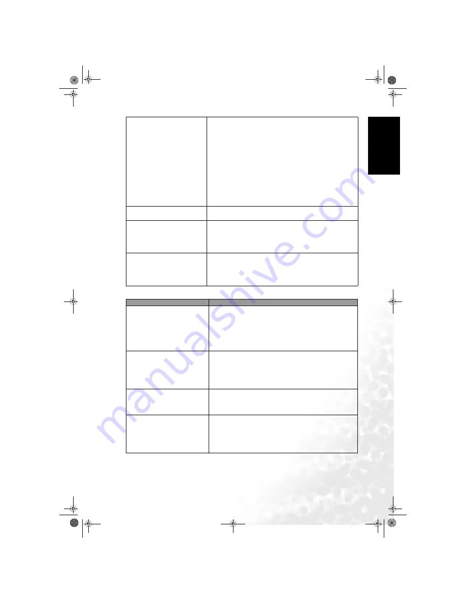
Antenna

Remote control does not 
function properly

• Check for incorrect battery orientation.
• Check for dead batteries
• Check your distance and angle from the display.
• Check whether remote control is properly being pointed at 

the display's remote control sensor window.

• Check for any obstacle between the remote control and the 

remote control sensor window. 

• Check that the remote control sensor window is not under 

strong fluorescent lighting.

• Check for any devices (PC or personal digital assistant, 

PDA) nearby that transmit infrared signal which may cause 

interference to signal transmission between the remote 

control and the LCD display. Turn off the infrared function 

of these devices.

There is no picture or sound, 
just noise.

• Make sure the antenna cable is properly connected.
• Change programs to confirm if the symptom is still present.

Picture is not clear.

• Make sure the antenna cable is properly connected.
• Change programs to confirm if the symptom is still present.
• If PC is selected as the input signal source, use the Auto 

function in the Picture Menu to let the display adjust 

picture automatically. Select Real as the display aspect ratio.

No sound.

• Check whether you have selected Mute for Audio setting.
• Make sure the volume is not set to minimum.
• Check the AV cables for disconnection.
• Check to see that the Speaker Out option is set to 'Off' in 

the Audio menu.

Symptoms

Possible Causes

The picture is not sharp or the 
picture contains image 
movement.

• The reception may be weak.
• Change programs to confirm if the symptom is still 

present.

• Make sure the outside antenna is not disconnected.
• Make sure the antenna is facing the right direction. 

If the antenna is exterior, have a suitable qualified and 

experienced antenna specialist adjust the antenna.

The picture is doubled or tripled

• Make sure the antenna is facing the right direction.
• Picture ghosting is caused by reflections from buildings, 

large metal structures and mountains. Carefully realign 

your antenna to minimise the ghost images. Ultimately a 

higher quality antenna professionally installed may be 

necessary to reduce the ghosting.

The picture is spotted

• There may be interference from automobiles, trains, high 

voltage lines, neon lights, etc.

• There may be interference between the antenna cable and 

power cable. Try positioning them further apart.

There are stripes on the screen or 
colours faded

• Is the display receiving interference from other devices? 

Transmission antennas of radio broadcasting stations and 

transmission antennas of amateur radios and cellular 

phones may also cause interference.

• Use the display as far away as possible from devices that 

may cause possible interference.

DV3251-En.book  Page 45  Monday, December 12, 2005  4:07 PM

Summary of Contents for DV3251

Page 1: ...ng Component Video source inputs 10 Connecting other Graphic source inputs 11 Display front view 11 Display control panel 12 External AV devices temporary terminal panel 13 Display rear view 14 Gettin...

Page 2: ...ting the HDMI input 24 Connecting the DVI input 24 Connecting the audio output 25 On Screen Display OSD menu 26 OSD structure 26 Navigating the OSD menu 26 Audio menu 27 Advanced Audio Settings 27 Pic...

Page 3: ...ted PC D Sub DVI Input Signal Timing 40 Supported Video Component DVI Input Signal Timing 40 Aspect ratio behaviour 41 16 9 41 4 3 41 Letterbox 42 Wide 42 Real 43 Troubleshooting 44 TV 44 Antenna 45 D...

Page 4: ...Table of Contents iv English Memo DV3251 En book Page iv Monday December 12 2005 4 07 PM...

Page 5: ...Welcome English V32S DV3251 DV3253 LCD Display Section 1 Quick Start Guide DV3251 En QuickStartGuide fm Page 1 Tuesday December 13 2005 2 03 PM...

Page 6: ...op of the display Follow the instructions on the carton to remove the upper carton from the base If you haven t done so already carefully unpack the display and accessories located in the top foam pac...

Page 7: ...like in front of an open window where rain water may enter If wall mounting allow at least 30mm space on top for attaching the display to the wall bracket It slides in and down onto the bracket from...

Page 8: ...outlet and switch it on if switched The display will enter standby mode and the power indicator on the front lower right will light up red The type of power cable plug and socket illustrated may diffe...

Page 9: ...to the remote control sensor window on the display Turn the remote control end up to reveal its base and open the lid of the battery compartment by using a small coin or similarly curved object to ro...

Page 10: ...chosen your Language Country and TV Standard select the Auto Installation menu item and then press the OK button on the remote control After a short pause the display will start searching for availabl...

Page 11: ...e display and the remote control describes how to connect other devices and provides product specifications and troubleshooting information for your further assistance Press the Program or Program but...

Page 12: ...Section 1 Quick Start Guide 8 English Memo DV3251 En QuickStartGuide fm Page 8 Tuesday December 13 2005 2 03 PM...

Page 13: ...Welcome English V32S DV3251 DV3253 LCD Display Section 2 User s Manual DV3251 En book Page 9 Monday December 12 2005 4 07 PM...

Page 14: ...TV Antenna BNL Video source inputs include 2 x S Video 2 x Composite Video and 2 x SCART Graphic source inputs include 2 x Component Video Y Pb Pr or Y Cb Cr 1 x HDMI DVI and 1 x PC D Sub You should c...

Page 15: ...me Description 1 Speakers High fidelity speakers for generating sounds 2 Power indicator Lights up green when the display is powered on Lights up red when the display is in standby mode Flashes red wh...

Page 16: ...next tuned TV program Performs the same action as the Program buttons on the remote control In the OSD menu moves the selection highlight up or down Performs the same action as the arrow up down butto...

Page 17: ...osite video output of your AV device AUDIO L R audio inputs Connect to the audio output of your AV device This input is common for either Video or S Video audio S VIDEO S Video input Connect to the S...

Page 18: ...Cr Pr Cb Pb Connect each to the component video Y Cb Pb Cr Pr outputs of appropriate video source devices 7 COMPONENT 1 AUDIO Connect each to the component audio outputs of appropriate video source de...

Page 19: ...our antenna TV CATV cable system 12 AV1 SCART AV2 SCART Connect each to the SCART output of up to 2 separate AV source devices AV1 is full SCART compliant and also accepts gaming RGB AV2 is AV input S...

Page 20: ...e selected See TV sound mode selection on page 18 When Teletext is displayed on the screen press this button to select the corresponding colour Teletext page See Using the Teletext function on page 20...

Page 21: ...creen image aspect ratio See Adjusting aspect ratio on page 19 18 Program Press these buttons to sequentially change programs See Changing programs on page 18 When Teletext is displayed on the screen...

Page 22: ...signal is connected to the HDMI input Adjusting volume Adjusting the volume 1 Press the Volume button on your display or press the Volume button on your remote control to increase volume The volume i...

Page 23: ...ing aspect ratio There may be situations where you select an image source which has a different aspect ratio to your screen This model display has a true widescreen TV 16 9 aspect ratio and so when vi...

Page 24: ...button to display the signal information including input video signal source Video format TV sound and current selected program The information displayed varies according to the input source being se...

Page 25: ...l on the display to the SCART terminal on the AV equipment using a SCART cable not provided Connect the AV1 or AV2 SCART terminal on the display to the SCART terminal on the AV equipment using a SCART...

Page 26: ...mposite video signals for example most VCRs analog Camcorders and game consoles 1 Connect the S Video output of your AV equipment to the display s AV3 S VIDEO terminal using the S Video cable not prov...

Page 27: ...alog video signal types Component Video offers the best quality Ensure the connector colours match as failure to connect the correct colours of the cables to the corresponding coloured terminals will...

Page 28: ...on formats such as NTSC or PAL It also supports Dolby 5 1 audio and high resolution audio formats 1 Connect the digital video output of your equipment to the HDMI terminal on the display using a DVI t...

Page 29: ...utlet you may wish to mute the built in speakers See Audio menu on page 27 Connect the AUDIO OUT L R terminals on the display to the audio input terminals of an amplifier or other audio device using a...

Page 30: ...dow TV Setup PIP Video Input Graphics Input PIP Audio Country Standard Auto Installation Manual Installation Program Edit Child Lock Language Freeze Backlight Sleep Timer DPMS DVI Input Reset All Sett...

Page 31: ...teady Sound Automatically adjusts the sound level to be constant amongst different TV stations when viewing TV programs Off Auto Speaker Out Enables sound output from the display s speakers when set t...

Page 32: ...zed picture mode If Personal is selected you can adjust the Contrast Brightness Colour and Sharpness settings individually to your satisfaction This option will not appear when PC or DVI via the HDMI...

Page 33: ...black level in NTSC video This option is not available for PAL video sources Use the and buttons on the remote control or the Volume and Vol ume buttons on the dis play to change the selection 0 7 5...

Page 34: ...he image contrast ratio for interlaced inputs only This option will not appear when PC DVI via the HDMI input HDMI or HD Component Video 720p or 1080i is the signal source Low Middle High Off Noise Re...

Page 35: ...ntrol or the Volume and Volume buttons on the display to change the selection Full Screen Video On Graphic Video Input Select the video signal input source for the PIP function This option is availabl...

Page 36: ...9 and responds to direct single numeric button program changing commands Use the and buttons on the remote control or the Volume and Volume buttons on the display to change the selection UK France Net...

Page 37: ...uning system If the tuned program is incorrect press the or button again until your desired program is located You can directly input the frequency using the program selection buttons if you wish 5 Pr...

Page 38: ...Press the button to highlight PR Swap and then press the direct access program selection buttons to select the new location for the program Two digit entry is required For example press 02 to select C...

Page 39: ...Child Lock menu will appear 2 You will be prompted to enter the password default password 0000 Enter the password using the program selection buttons When entering you can press the button to clear a...

Page 40: ...ambient light sensor will be activated and the display s backlight will be changed automatically according to the ambient lighting condition Auto Dark Normal Bright Sleep Timer Set the Sleep timer to...

Page 41: ...characteristics Do not mix different types Do not mix old and new batteries Mixing old and new batteries will shorten battery life and or cause chemical leaks from the old batteries When batteries fa...

Page 42: ...Reference 38 English Dimensional drawings Unit mm DV3251 En book Page 38 Monday December 12 2005 4 07 PM...

Page 43: ...Composite video RCA Composite video SCART Cenelec Component video Y PB CB PR CR Audio input Graphic HDMI DVI via HDMI PC D sub PC DVI audio Signal outputs RCA type audio output Minijack type headphone...

Page 44: ...y Mhz Note 720 x 400 31 467 70 082 28 32 VGA 640 x 480 31 469 59 94 25 175 VGA 640 x 480 37 861 72 819 31 5 VGA 640 x 480 37 5 75 31 5 VGA 800 x 600 37 9 60 317 40 SVGA 800 x 600 48 077 72 188 50 SVGA...

Page 45: ...e resultant displayed image aspect depending upon the aspect of the image source 16 9 is most suitable for images which are already in a 16 9 aspect like HDTV as it displays them without any aspect al...

Page 46: ...d letterbox presentation format which is created from a 16 9 aspect ratio image scaled down proportionally to fit into a 4 3 aspect display frame resulting in black unlit horizontal bars visible on th...

Page 47: ...s displayed and none is cropped or lost Real Displays the image in a one to one pixel mapping in the centre of the screen without alteration or resize Original source video image Resultant displayed v...

Page 48: ...your antenna to reduce the affects of the interference If the antenna is exterior have a suitable qualified and experienced antenna specialist adjust the antenna Degraded colours or hue Check whether...

Page 49: ...minimum Check the AV cables for disconnection Check to see that the Speaker Out option is set to Off in the Audio menu Symptoms Possible Causes The picture is not sharp or the picture contains image...

Page 50: ...Reference 46 English Memo DV3251 En book Page 46 Monday December 12 2005 4 07 PM...

Reviews: