


12
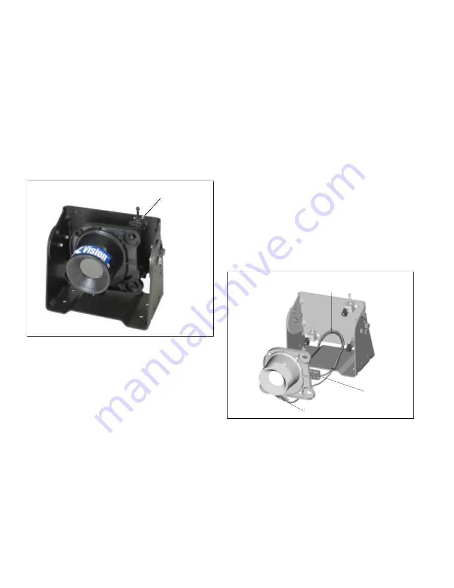
FIGURE 22 - FULLY ASSEMBLED IR CAMERA
Aiming Assembly
Attach the IR camera to the IR camera bracket
13. Position the IR camera onto the factory-installed aiming
assemblies. Refer to Figure 22.
14. Rotate the pivot locks on the ends of the aiming
assemblies 1/4 turn clockwise, using the included
aiming adjuster tool. This will lock the IR camera in
position.
15. Adjust the harness, ensuring that it is not pulled tight,
which could cause a water leak into the camera.
Securely tighten the harness cable tie to prevent wire
chaffing from the bracket.
16. Aim and adjust the IR camera. Refer to
Aiming the IR
Camera
on pages 21 and 22.
IR CAMERA
Maintaining
The IR camera weighs approximately 2 lbs. Conduct the
following maintenance inspections on a regular basis.
1. Inspect the harnessing for chafing.
2. Inspect mounting for loose bolts.
3. Inspect aiming adjusters for cracks or breaks. Replace
as necessary.
4. Inspect and clean the camera window.
Replacing IR Camera
1. Unlock the IR camera by turning the two IR camera
aiming adjusters and the IR camera standoff
1/4 turn counterclockwise.
2. Remove the IR camera from the IR camera bracket to
get easier access to the connectors.
3. Disconnect the 6-pin IR camera connector and the 2-pin
window heater connector of the IR camera harness from
the IR camera.
4. Install new camera. Plug the 2-pin connector of the IR
camera harness into the window heater. Refer to Figure
23.
Cable Tie
6-pin connector
2-pin connector
FIGURE 23 - CONNECTING THE IR CAMERA HARNESSES
5. Plug the 6-pin connector of the IR camera harness into
the IR camera connection. Refer to Figure 23.
6. Position the IR camera onto the factory-installed
aiming adjusters.
7. Rotate the pivot locks (on the ends of the aiming
adjusters) 1/4 turn clockwise, using the included aiming
adjuster tool. This will lock the IR camera in position.
Summary of Contents for XVision
Page 23: ...23 FIGURE 43 ELECTRICAL WIRING DIAGRAM FOR XVISION SYSTEM ...
Page 26: ...26 NOTES ...
Page 27: ...27 NOTES ...


