background image

isoNAV685-D_D00215_02_M_XXEN/04.2017

6

Important information

1.  Important information

1.1 How to use this manual

Always keep this manual within easy reach for future reference.
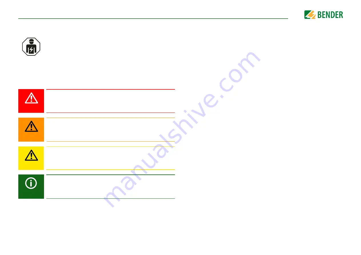
To make it easier for you to understand and revisit certain sections in this manual, we 
have used symbols to identify important instructions and information. The meaning of 
these symbols is explained below:

This manual is intended for 

qualified personnel

 working in electrical en-

gineering and electronics!

This signal word indicates that there is a 

high risk of danger

 that will re-

sult in 

electrocution

 or 

serious injury

 if not avoided.

This signal word indicates a 

medium risk of danger

 that can lead to

death

 or 

serious injury

 if not avoided.

This signal word indicates a 

low level risk

 that can result in 

minor or mo-

derate injury

 or 

damage to property

 if not avoided.

This symbol denotes information intended to assist the user in making

optimum use

 of the product.

DANGER

WARNING

CAUTION

1.2 Technical support

For commissioning and troubleshooting Bender offers you:

 1.2.1  First level support

Technical support by phone or e-mail for all Bender products
    • Questions concerning specific customer applications
    • Commissioning
    • Troubleshooting

Telephone: 

+49 6401 807-760*

Fax:


+49 6401 807-259

In Germany only: 

0700BenderHelp (Tel. and Fax)

E-mail: 

[email protected]

 1.2.2  Repair service

Repair, calibration, update and replacement service for Bender products
    • Repairing, calibrating, testing and analysing Bender products
    • Hardware and software update for Bender devices
    • Delivery of replacement devices in the event of faulty or incorrectly delivered 

Bender devices

    • Extended guarantee for Bender devices, which includes an in-house repair service or 

replacement devices at no extra cost

Telephone

+49 6401 807-780** (technical issues)
+49 6401 807-784**, -785** (sales)

Fax:


+49 6401 807-789

E-mail: 

[email protected]

Please send the devices for 

repair

 to the following address:

Bender GmbH, Repair-Service,
Londorfer Strasse 65,
35305 Grünberg

Summary of Contents for ISOMETER isoNAV685-D

Page 1: ...EN Manual isoNAV685 D_D00215_02_M_XXEN 04 2017 ISOMETER isoNAV685 D Insulation Monitoring Device for IT AC systems with galvanically connected rectifiers and inverters ...

Page 2: ...o KG All rights reserved Reproduction only with permission of the publisher Subject to change Customer service Service hotline 0700 BenderHelp Telephone and Fax Carl Benz Straße 8 35305 Gruenberg Germany Tel 49 6401 807 760 Fax 49 6401 807 629 E Mail info bender service com PLEASE READ THIS MANUAL AND ANY ACCOMPANYING DOCUMENTS CAREFULLY AND KEEP THEM IN A SECURE PLACE FOR FUTURE REFERENCE ...

Page 3: ...4 2 Connections and panel 13 4 3 Display elements and device buttons 14 5 Mounting 15 5 1 General instructions 15 5 2 Screw mounting 15 5 3 DIN rail mounting 16 6 Connection 16 6 1 Connection requirements 16 6 2 Connection to a 3 N AC system 18 6 3 Connection to the X1 interface 18 6 4 Connection to the supply voltage 19 6 5 Connection to the Ethernet interface 19 6 6 Connection to the relay 1 int...

Page 4: ...tion 2 32 10 1 1 9 3 4 Function 3 32 10 1 1 9 4 Digital 2 32 10 1 1 9 5 Buzzer 32 10 1 1 9 5 1 TEST 32 10 1 1 9 5 2 Function 1 32 10 1 1 9 5 3 Function 2 32 10 1 1 9 5 4 Function 3 32 10 1 1 9 6 Analogue 33 10 1 1 9 6 1 Mode 33 10 1 1 9 6 2 Midscale 33 10 1 1 9 6 3 TEST 33 10 1 1 9 6 4 Function 33 10 1 2 0 Data measured values 34 10 1 3 0 Control 34 10 1 4 0 History 34 10 1 5 0 Device settings 34 ...

Page 5: ... inverter 10 Hz 43 13 3 Response time profile inverter 10 Hz 44 13 4 Relative uncertainty 44 14 Alarm messages 45 15 Factory settings 46 16 Technical data 47 16 1 Tabular data 47 16 2 Standards and certifications 50 16 3 Ordering details 50 17 Glossary 51 18 Modbus settings 52 18 1 General information 52 18 2 Data access by means of Modbus TCP Protokoll 52 18 2 1 Exception code 52 18 2 2 Modbus re...

Page 6: ...ser in making optimum use of the product DANGER WARNING CAUTION 1 2 Technical support For commissioning and troubleshooting Bender offers you 1 2 1 First level support Technical support by phone or e mail for all Bender products Questions concerning specific customer applications Commissioning Troubleshooting Telephone 49 6401 807 760 Fax 49 6401 807 259 In Germany only 0700BenderHelp Tel and Fax ...

Page 7: ...try set out by the ZVEI Zentralverband Elektrotechnik und Elektronikindustrie e V German Electrical and Electronic Manufacturer s Association also applies Sale and delivery conditions can be obtained from Bender in printed or electronic format 1 5 Inspection transport and storage The devices must only be stored in areas where they are protected from dust damp and spray and dripping water and in wh...

Page 8: ...ty information Make sure that the basic settings meet the requirements of the IT system Children and unauthorised persons must not have access to or contact with the ISOMETER Make sure that the operating voltage is correct Prior to insulation and voltage tests the ISOMETER must be disconnected from the IT system for the duration of the test In order to check the correct connectionofthedevice afunc...

Page 9: ...frequency inverters 2 20 kHz 2 4 Intended use The ISOMETER isoNAV685 D monitors the insulation resistance of unearthed AC main circuits IT systems with input voltages of AC 0 690 V and a frequency of 60 Hz in the three phase network DC components existing in AC DC systems do not influence the operating characteristics Due to the separate supply voltage de energised systems can also be monitored Th...

Page 10: ...nse value Because of these characteristics the ISOMETER can for example quickly shut down a plant To obtain a measurement the device has to be connected between the IT system un earthed system and the protective earth conductor PE A measuring current in the µA range is superimposed onto the system which is recorded and evaluated by a micro con trolled measuring circuit The measuring time is depend...

Page 11: ...s the connections to the IT system and earth The self test can also be activated manually by means of the test button to check the func tions of the relays depending on the configuration or it can be selected via the Control menu refer to Control on page 34 The progress of the manual self test is shown on the LC display by a bar graph Depending on the conditions in the IT system being monitored th...

Page 12: ...isoNAV685 D_D00215_02_M_XXEN 04 2017 12 4 Device overview 4 1 Dimensions 108 mm 110 mm m m 3 9 ...

Page 13: ...o the IT system to be monitored L3 Connection to the IT system to be monitored KE E Connection to PE Top ON Display RESET DATA LEDs SERVICE ALARM 1 ALARM 2 MENU ESC TEST INFO OK X3 X3 Optional expansion module for Bender devices e g BB Bus ETH X1 Digital interface ETH Ethernet interface R Selectable resistance R 11 12 14 Connector for alarm relay 1 21 22 24 Connector for alarm relay 2 Bottom ...

Page 14: ...tion resistance of the IT system falls below the set response value Ran2 and the DC offset voltage exceeds the response value 1 7 8 9 10 11 2 3 4 5 6 Device buttons You can adjust the device settings in the respective menu using the menu buttons Depending on the menu entry one of the options displayed below is assigned to the buttons 6 MENU Opens the device menu ESC Cancels the current process or ...

Page 15: ...lectrical installation Destruction of the device Before installing and connecting the device make sure that the in stallation has been de energised Observe the rules for working on elec trical installations DANGER 5 2 Screw mounting 19 Fix the three mounting clips delivered with the device two of them packed separa tely manually or using a tool as illustrated below 20 Drill the mounting holes for ...

Page 16: ...ical installation Destruction of the device Before installing and connecting the device make sure that the in stallationhas been de energised Observe the rules for working on elec trical installations Risk of electric shock Nominal voltages up to 1000 V may be present on the terminals L1 to L3 which can be lethal Make sure the terminal covers are properly mounted and clicked in before putting the ...

Page 17: ...nsulation monitoring device is con nected in each conductively connected system Risk of property damage due to unprofessional installation The connecting lines L1 L2 L3 to the system to be monitored must be carried out as spur lines Inadmissible load current can result in damage to property and personal injury Do not apply any load current to the ter minals Check proper connection Prior to commiss...

Page 18: ...d to the IT system to be monitored can be omitted if the wiring is carried out in such a manner as to reduce the risk of a short circuit to a minimum Ensure short circuit proof and earth fault proof wiring WARNING L1 L2 L3 N PE US Un 6 3 Connection to the X1 interface Position the terminal cover and click it into place I1 I2 I3 A B M Q2 Q1 Electrical overload protection Auto shut off in the event ...

Page 19: ...ing longer than 1 m the use of a shielded cable is prescribed Danger of damage to property due to faulty connections The device can be damaged if the unit is simultaneously connected to the supply voltage via the X1 interface and A1 and A2 terminals Do not connect the device simultaneously via X1 and A1 and A2 to different supply voltages CAUTION US 6 5 Connection to the Ethernet interface Positio...

Page 20: ... 11 12 14 Position the terminal cover and click it into place 11 12 14 Relay 1 Common contact Normally open n o Normally closed n c 6 7 Connection to the relay 2 interface 21 22 24 Position the terminal cover and click it into place 21 22 24 Relay 2 Common contact Normally closed n c Normally open n o ...

Page 21: ...easurement and outputs the measured insulation resistance values of the IT system being monitored then commissioning is completed For customer specific configured devices the commissioning wizard might be deactivated and cannot be run In this case the device is preset However the commissioning wizard can be started as described at Recommissioning on page 22 Observe device status The device is in a...

Page 22: ...sioning and initial measurement by ad hering to the response values set 8 Display 8 1 Standard display During normal operation the ISOMETER displays the message OK and below the currently measured insulation resistance In the bottom line of the display the set limit values for R an are indicated In the example shown below Ran 5 kΩ The signal quality of the measurement suits the selected profile Th...

Page 23: ...of 150 V has been exceeded Alarm 1 and Alarm 2 have been trig gered In addition information concerning the DC shift is also displayed If several fault messages occur you can navigate through the faults using the and buttons ALARM 1 lights Insulation fault ALARM 1 2 lights Insulation fault DC shift error ALARM 1 2 blinks Connection fault SERVICE lights up Device fault 3 kΩ Insulation fault 1 4 3 kΩ...

Page 24: ...2 28 03 14 17 18 2 4 7 kΩ 7 kΩ 8 4 Acknowledge fault memory In order to acknowledge the fault message and return to the ISOMETER s standard display all faults must be acknowledged by means of the reset button This means that fault messages can only be reset when the cause of the fault has been eliminated Press the reset button then and OK to clear the fault memory The ISOMETER then returns to the ...

Page 25: ...d by these values 1 0 100 010 001 MΩ Stunde 16 26 16 52 Data isoGraph 2 1 4 Change parameter value Leave view Modify scale Modify scale Change parameter value Current time scale 8 6 History memory Up to 1023 alarm messages and device errors are stored in the history memory with date and time stamp When the history memory is deleted the minimum insulation resistance Rmin will also be reset at Menu ...

Page 26: ...tial measurement During the initial measurement the device records all measured values All measured values that may have been recorded before will be discarded if a new initial measurement is started IT System R an 40kΩ 10kΩ Initial measurement Initial measurement ...

Page 27: ...3 Digital 1 1 Test 2 Mode 3 Function 1 4 Function 2 5 Function 3 4 Digital 2 1 Test 2 Mode 3 Function 1 4 Function 2 5 Function 3 4 Memory 4 Coupling 5 Summer 1 Test 2 Function 1 3 Function 2 4 Function 3 2 Data meas values 3 Control 4 History 5 Device settings 1 Language 2 Clock 1 Time 2 Format 3 Summer time 4 Date 5 Format 3 Interface 1 Write access 2 Ethernet 1 DHCP 2 IP 3 SN 4 Std GW 5 DNS Ser...

Page 28: ...You can move to the left or the right to set different values using the and buttons The value po sitioned between the symbols is the val ue that is set Text input Go step by step through the numbers and letters indicated on the display by using the button forwards and the button backwards Navigate to the right using the button to enter the next character To delete a character that has been en tere...

Page 29: ...memory The fault memory can not be deactivated If a fault becomes inactive the programmed outputs remain in a fault condition until they are manually reset 10 1 1 2 Profile Adapt the area of application of the ISOMETER to your system profile For a description of the profiles refer to Device profiles on page 42 The following can be selected 10 1 1 3 System type Especially for the ISOMETER isoNAV685...

Page 30: ...Coupling monitoring of L1 L2 L3 is turned off Active high An event is carried out on the rising edge of the digital input low to high Response time t on t off after a switch on signal I2 I3 A B M Q2 Q1 Device inactive Reset Test I1 Ix X1 X1 10 1 1 8 1 2 t on The response time t on after a switch on signal can be set between 100 milliseconds and 300 seconds refer to 10 1 1 8 1 1 Mode 10 1 1 8 1 3 t...

Page 31: ...N O Normally opened N O operation contacts 11 12 14 21 22 24 infault free condition the alarm relay isde energised 10 1 1 9 1 3 Function 1 Up to three functions can be assigned to one output The functions are linked to an OR operator Select the appropriate setting for function 1 The following parameters can be set 10 1 1 9 1 4 Function 2 Refer to 10 1 1 9 1 3 Function 1 off The function is not use...

Page 32: ...X1 iso685 Qx X1 iso685 Qx oder X1 iso685 Qx X1 iso685 Qx internal external 10 1 1 9 3 2 Function 1 Refer to 10 1 1 9 1 3 Function 1 10 1 1 9 3 3 Function 2 Refer to 10 1 1 9 1 3 Function 1 10 1 1 9 3 4 Function 3 Refer to 10 1 1 9 1 3 Function 1 10 1 1 9 4 Digital 2 Refer to 10 1 1 9 3 Digital 1 10 1 1 9 5 Buzzer The following parameters can be set for the buzzer 10 1 1 9 5 1 TEST The functional t...

Page 33: ...sing the analogue output 10 1 1 9 6 3 TEST The functional test of the analogue output can be activated or deactivated In this way the analogue output is adjusted once for the entire range This only applies to the manual test and not to the cyclic device self test 10 1 1 9 6 4 Function Select the appropriate setting for the analogue output The following parameters can be set Lower value Analogue ou...

Page 34: ...leakage capacitance IT system data Displays the system phase to phase voltages and the mains fre quency r m s values IT system data Displays the system phase to earth voltages TEST Manual device test RESET Reset of fault and alarm messages Start initial measurement All recorded measurements are discarded and a new measurement is started History Overview of faults that have occurred Delete Reset th...

Page 35: ... NTP Select if you would like to synchronise the current time via NTP You have to configure the NTP server in order to use this function see NTP server on page 35 10 1 5 2 7 NTP server Set the IP address of the NTP server 10 1 5 2 8 UTC Set the time according to UTC coordinated world time For Germany set 1 for winter time MEZ and 2 for summer time MESZ 10 1 5 3 Interface Set the parameters for the...

Page 36: ...nguish it from another in the system and ensure correct communication 10 1 5 3 3 4 Timeout Set the timeout for messages between 100 ms 10 s This time specification defines the maximum permissible time for a device to respond 10 1 5 3 3 5 TTL for subscription Set a time between 1 s 1092 min This time defines the intervals at which the ISOMETER sends messages to e g a gateway Severe alarms e g insul...

Page 37: ...n only be accessed by Bender Service staff 10 1 6 0 Info The ISOMETER s current settings can be viewed in the Info menu Navigate through the different views using the and buttons on Password query active off Password query inactive Save The ISOMETER saves your device settings Restore The ISOMETER restores your initial device settings Device Device name serial number article number Software Softwar...

Page 38: ...ork e g for parameter setting etc but it cannot communicate with other devices 11 3 Modbus TCP Modbus is an international widely used protocol for data transfer between devices All measured values messages and parameters are stored in virtual register addresses Data can be read out with a read command on the register address With a write com mand data can be written into a register address The reg...

Page 39: ...ameter setting of the device Easy assignment and edition options of device and measuring channel texts Maintenance Data storage of specific events for fast support by Bender Service A maximum of 5 TCP IP connections can be used simultaneously Only one device may access the web server at the same time If several de vices try to access the web server it may result in timeouts Web server device menu ...

Page 40: ...Device communication isoNAV685 D_D00215_02_M_XXEN 04 2017 40 Web server user interface 5 6 10 9 7 8 ...

Page 41: ...on of Modbus information for the individual parameters To be able to see this information the selection box at PARAMETER ADDRESSES 4 for the question Display additional Modbus informa tion for each parameter must be activated 8 System OK alarms Indication of the system status System OK green button and Alarms red button If there are pending alarms click on the red button or go to menu point ALARMS...

Page 42: ...nverter 10 Hz or Inverter 10 Hz Inverter 10 Hz AC 0 690 V DC 0 1000 V 10 460 Hz 0 20 µF 50 V This profile is used for systems with dynamic frequency control by inverters in the range 10 to 460 Hz in order to optimise the measurement with respect to the measuring time and quality Inverter 10 Hz AC 0 690 V DC 0 1000 V 1 460 Hz 0 20 µF 50 V For systems involving extremely low frequency control in the...

Page 43: ...ion of the response value Ran and system leakage capacitance Ce according to IEC 61557 8 Un AC 690 V fn 60 Hz 1 10 100 10000 1000 100 10 1 Response time sec Response value Ran kΩ Ce 20 μF Ce 5 μF Ce 1 μF Response time as a function of the response value Ran and system leakage capacitance Ce according to IEC 61557 8 Un AC 690 V fn 60 Hz 1 10 100 10000 1000 100 10 1 Response time sec Response value ...

Page 44: ... of the response value Ran and system leakage capacitance Ce according to IEC 61557 8 Un AC 690 V fn 60 Hz H ื w H ื w H ื w 0 10 20 30 40 50 60 70 80 90 100 0 0 0 0 0 1 0 0 0 0 1 0 0 0 1 0 0 1 0 1 1 1 0 Operating uncertainty Ce 150μF Ce 1μF Relative uncertainty as a function of the response value Ran and system leakage capacitance Ce according to IEC 61557 8 Un AC 690 V fn 60 Hz ...

Page 45: ...n terminals E and KE to earth PE Check the wiring of terminals E and KE to earth PE Press the test button Connection on page 16 ALARM 1 ALARM 2 flash in common mode Service mode active The device is in maintenance condition Contact Bender Service SERVICE lights up The profile does not suit the application Wrong profile selected for this application Check measured system capacitance or mains freque...

Page 46: ...tart up delay Tstart up 0 s Digital inputs Digital input 1 Mode Operating mode Active high Function Deactivate device Digital input 3 Mode Operating mode Active high Function Deactivate device Digital outputs Digital output 1 Function 1 Insulation fault DC offset voltage Switching elements Relay 1 Operating mode N C operation Function 1 Ins alarm 1 Relay 2 Operating mode N C operation Function 1 I...

Page 47: ... typically 50 60 Hz 12 W 21 VA Power consumption typically 400 Hz 12 W 45 VA Supply via X1 Supply voltage Us DC 24 V ToleranceofUs DC 20 25 IT system being monitored Nominal system voltage range Un AC0 690V DC 0 1000 V AC DC 0 600 V for UL applications Tolerance ofUn AC DC 15 Frequency range of Un 60Hz Response values Response value Ran1 alarm 1 1 kΩ 10 MΩ Response value DC residual voltage Alarm ...

Page 48: ...ver Modbus TCP BCOM Data rate 10 100 Mbit s autodetect Max amount Modbus requests 100 s Cable length 100 m Connection RJ45 IP address DHCP manual 192 168 0 5 Network mask 255 255 255 0 BCOM address system 1 0 Function communicationinterface Switching elements Number of switching elements 2 changeover contacts Operating mode N C operation N O operation Contact 11 12 14 none insulationAlarm1 insulat...

Page 49: ... mm flexible with TWIN ferrule with plastic sleeve 0 25 0 75 mm Other Operating mode continuousoperation Mounting 0 display oriented cooling slots must be ventilated vertically6 Degree of protection internal components IP40 Degreeof protection terminals IP20 DIN rail mounting acc to IEC 60715 Screw fixing 3 x M4 with mounting clip Enclosure material polycarbonate Flammability class V 0 ANSIcode 64...

Page 50: ... included in the scope of delivery Suitable system components SKMP midscale point Type Supply voltage US Art No isoNAV685 D AC 24 240 V 50 400 Hz B91067014 Description Art No iso685 Mechanical accessories comprising Terminal cover and 2 mounting clips B91067903 iso685 Plug kit screw terminals B91067901 iso685 plug kit with push wire terminals B91067902 Description Type Art No Suitable measuring in...

Page 51: ...e entire installation that is visible for the customer and defined by the customer The BCOM communication takes place within this system Naturally different systems can exist independently in one network Subsystem BCOM The subsystem structures parts of the system as units defined by the customer e g all PQ devices A typical subsystem are also non BCOM capa ble devices that are hidden behind a prox...

Page 52: ...es a function related response and sends it to the Modbus client Maximum of Modbus TCP requests per second 100 s 18 2 1 Exception code If a request cannot be answered for whatever reason the server sends a so called excep tion code to limit possible errors 18 2 2 Modbus request By means of the function code FC3 the required information in Words can be read from the ISOMETER iso685 input registers ...

Page 53: ...Register 0 0x1234 fictitous value Byte 11 12 Value in Register 1 0x2345 fictitous value Byte Name Example Byte 7 Modbus function code 0x83 Byte 8 Exception code 0x01 or 0x02 18 3 Measuring value information 18 3 1 High byte test status 18 3 2 Low byte alarm status 18 3 3 High byte range 18 3 4 Low byte unit Value Description 0 No test 1 Internal test 2 External test Value Description 0 No alarm 1 ...

Page 54: ...soNAV685 D_D00215_02_M_XXEN 04 2017 54 5 Percent 6 Hertz 7 Baud 8 Farad 9 Henry 10 Degree Celsius 11 Degree Fahrenheit 12 Second 13 Minute 14 Hour 15 Day 16 Month 17 Watt 18 var 19 VA 20 Wh 21 varh 22 Vah 23 Degree 24 Hertz per second ...

Page 55: ...he interface unit 0x571 1393 Software Version interface 2 Uint16 RO 0x578 1400 D number measuring technique 2 Uint16 RO Software number of the measuring technique 0x579 1401 Software version measuring technique 2 Uint16 RO Measuring values 0x1010 4112 Channel number 1 num ber Uint16 RO 0x1011 4113 Insulation value 4 Float RO Insulation value Ω 0x1013 4115 Test and alarm status 2 Uint16 RO High byt...

Page 56: ...3 V 0x1053 0x105F 4179 4191 See previous channel RO 0x1060 4192 Channel number 6 2 Uint16 RO 0x1061 4193 Voltage L2 L3 4 Float RO Voltage measured between phase L2 and phase L3 V 0x1063 0x106F 4195 4207 See previous channel RO 0x1070 4208 Channel number 7 2 Uint16 RO 0x1071 4209 Voltage L1 PE 4 Float RO Voltage measured between phase L1 and PE V 0x1073 0x107F 4211 4223 See previous channel RO 0x10...

Page 57: ... 4307 4319 See previous channel RO 0x10E0 4320 Channel number 14 2 Uint16 RO 0x10E1 4321 Device error 4 Float RO Device error number e g 750 7 50 Communication CAN 0x10E3 0x10EF 4323 4335 See previous channel RO 0x10F0 4336 Channel number 15 2 Uint16 RO 0x10F1 4337 DC Offset 4 Float RO DC shift in the system 0 Fault on DC 100 Fault on DC 0x10F3 0x10FF 4339 4351 See previous channel RO 0x1100 4352 ...

Page 58: ... 25 Fault on DC 25 75 Symmetrical fault 75 100 Fault on DC 0 100 0x1123 0x112F 4387 4399 See previous channel RO 0x1130 4400 Channel number 19 2 Uint16 RO 0x1131 4401 DC minus alarm 4 Float RO See 0x1121 0x1133 0x113F 4403 4415 See previous channel RO 0x1140 4416 Channel number 20 2 Uint16 RO 0x1141 4417 DC plus alarm 4 Float RO See 0x1121 0x1143 0x114F 4419 4431 See previous channel RO Register a...

Page 59: ...ured between L2 and PE V 0x2010 8208 Voltage L3 PE 4 Float RO Voltage measured between L3 and PE V 0x2012 8210 System frequency 4 Float RO Hz 0x2014 8212 System connection 4 Float RO 101 Error 0 OK 0x2016 8214 Connection to earth 4 Float RO 101 Error 0 OK 0x2018 8216 Device error 4 Float RO Device error number e g 750 7 50 Communication CAN 0x201C 8220 DC Offset 4 Float RO DC shift in the system 0...

Page 60: ...ed when DHCP off aaa bbb ccc ddd aaa 256 bbb 256 ccc 256 ddd 0 4 294 967 295 0x3003u 12291 Standard Gateway 4 Uint32 R W Configured gateway used when DHCP off aaa bbb ccc ddd aaa 256 bbb 256 ccc 256 ddd 0 4 294 967 295 0x3005u 12293 Subnet mask 2 Uint16 R W Configured subnet mask used when DHCP off Number of leading 1 s in the binary sub net mask e g 6 11111100 00000000 0000000 0 00000000 252 0 0 ...

Page 61: ...Uint16 R W Time interval in which a BCOM messages is sent from a device to the Gateway at the latest 0 65 535 s 0x3019u 12313 DNS server IP 4 Uint32 R W IP address of the DNS server aaa bbb ccc ddd aaa 256 bbb 256 ccc 256 ddd 0 4 294 967 295 0x301Bu 12315 DNS domain 250 String UTF 8 R W DNS domain a z0 9 Time 0x3098u 12440 Time 4 Unix Time R W 0x309Au 12442 0 4 0 R 0x309Cu 12444 Time zone 4 Float ...

Page 62: ...loat R W ON delay because of debounce 0 1 300 s 0x30A9u 12457 Digital Input 1 T off 4 Float R W OFF delay because of debounce 0 1 300 s 0x30ABu 12459 Digital Input 2 Function 2 Uint16 R W see 0x30A5u 0x30A9u 1 5 0x30ACu 12460 Digital Input 2 Mode 2 Uint16 R W see 0x30A5u 0x30A9u 1 2 0x30ADu 12461 Digital Input 2 T on 4 Float R W see 0x30A5u 0x30A9u 0 1 300 s 0x30AFu 12463 Digital Input 2 T off 4 F...

Page 63: ...8 0x30B9u 12473 Digital Output 1 Function 3 2 Uint16 R W see 0x30B7u 1 8 0x30BAu 12474 Digital Output 1 Mode 2 Uint16 R W 1 Passive 2 Active 1 2 0x30BBu 12475 Digital Output 1 Test 2 Uint16 R W 1 Test on 2 Test off 1 2 0x30BCu 12476 Digital Output 2 Function 1 2 Uint16 R W see 0x30B7u 0x30BBu 1 8 0x30BDu 12477 Digital Output 2 Function 2 2 Uint16 R W see 0x30B7u 0x30BBu 1 8 0x30BEu 12478 Digital O...

Page 64: ...tion 1 2 Uint16 R W see 0x30B7u 1 11 0x30C6u 12486 Summer Function 2 2 Uint16 R W see 0x30B7u 1 11 0x30C7u 12487 Summer Function 3 2 Uint16 R W see 0x30B7u 1 11 0x30C8u 12488 Summer Test 2 Uint16 R W 1 Test on 2 Test off 1 2 RelayOutFunctions 0x30C9u 12489 Relay 1 Test 2 Uint16 R W 1 Test on 2 Test off 1 2 0x30CAu 12490 Relay 1 Mode 2 Uint16 R W 1 N O 2 N C 1 2 0x30CBu 12491 Relay 1 Function 1 2 U...

Page 65: ...ins supply system 2 Uint16 R W 1 3AC 1 0x30D8u 12504 Profiles 2 Uint16 R W 1 Power circuits 2 Inverter 10Hz 3 Inverter 10Hz 1 3 0x30D9u 12505 Coupling monitoring 2 Uint16 R W 1 Coupling monitoring on 2 Coupling monitoring off 1 2 0x30DAu 12506 Coupling devices 2 Uint16 R W 1 No coupling device 1 0x30DBu 12507 Fault memory 2 Uint16 R W 1 Fault memory on 1 0x30DCu 12508 Start up delay 2 Uint16 R W 0...

Page 66: ...terface 19 Relay 1 interface 11 12 14 20 Relay 2 interface 21 22 24 20 Supply voltage 19 X1 interface 18 Coupling device 43 Coupling monitoring 30 D Data isoGraph 38 Date 35 Setting the date 34 Device buttons 14 DHCP 35 51 Diagrams 43 Display 14 22 Data isoGraph 38 Fault display active 23 Fault display inactive 23 Fault memory 24 History memory 25 Limit values for R an 22 Signal quality of the mea...

Page 67: ...ings 52 Modbus TCP 51 Modbus TCP 38 N Nominal system voltage 42 47 Nominal voltage 16 Normal operation 22 O Operating mode 30 Operation Buttons 21 Commissioning 17 21 Ordering information 50 Output 31 P Password 36 Product description 10 Profile overview 42 Protective earth conductor PE 16 R Response time Profile inverter 10 Hz 44 Profile power circuits 43 Relative uncertainty 44 Response value 47...

Page 68: ...AV685 D_D00215_02_M_XXEN 04 2017 68 Measured values 34 Profile 29 Sicherheitshinweise 55 Signal quality of the measurement 22 Start up delay 29 System leakage capacitance 9 10 42 T Technical data 47 W Web server 39 51 ...

Page 69: ...Benz Straße 8 35305 Gruenberg Germany Tel 49 6401 807 760 Fax 49 6401 807 629 E Mail info bender service com Web http www bender de BENDER Group Bender GmbH Co KG Postbox 1161 35301 Gruenberg Germany Londorfer Straße 65 35305 Gruenberg Germany Tel 49 6401 807 0 Fax 49 6401 807 259 E Mail info bender de Web www bender de ...

Reviews: