


Technical data
47
iso1685FR(M)_D00002_02_M_XXEN/06.2017
Other
Operating mode .......................................................................................................................................................................................................... continuous operation
Position of normal use................................................................................................................................................................................ vertical, system coupling on top
Degreee of protection, internal components.......................................................................................................................................................................................... IP30
Degree of protection, terminals .............................................................................................................................................................................................................. IP30
Software version ......................................................................................................................................................................................................................... D407 V1.13
Weight ................................................................................................................................................................................................................................................... 650 g
( )* = ......................................................................................................................................................................................................................................Factory settings
** = The specification refers only to the differential voltage between the coupling terminals, not to earth.
Higher voltages lead to a device fault notification (ADC overload), but not to a defect in the device.Maximum
permissible voltage between terminals L1 and L2 = 3.0 kV
*** =Corresponds to a maximum phase voltage of the system to be monitored of 5 kV.
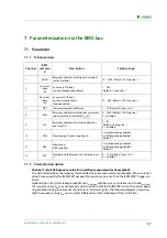
10.2 Factory settings
Special faetures of the iso1685FRM
Parameter Software
Value
Condition
can be set via
Insulation measurement response value Z
an
(Active method)
25 kΩ
BMS
Leakage capacitance of the installation C
e-Anlage
1 nF
BMS
Insulation resistance of the installation R
e-Anlage
180 kΩ
BMS
Measured data buffer size for |Z
e
| (active method)
4
BMS
Offset voltage response value
U
an
(passive method)
125 V
BMS
Response value of measured value suppression
(Interference detection active method)
15 %
BMS
Coupling monitoring system connection
1 (Monitoring enabled)
BMS
Monitoring earth connection E/KE
1 (Monitoring enabled)
BMS
Response value of the interference counter (actives
method)
6
BMS
Relay K1 (11/12/14)
N/C operation
-
Relay K2 (21/22/24)
N/C operation
-
BMS address
2
DIP switch
Parameterization lock
OFF (Lock off )
DIP switch 6
BMS termination
ON (Termination enabled)
Switch
"RS-485-Term."
Relay K3 (31/32/34)
N/C operation
-
RS485 protocol
Value
can be set via
BMS
OFF
DIP switch 1
Summary of Contents for ISOMETER iso1685FR
Page 6: ...6 ...
Page 10: ...Important information 10 iso1685FR M _D00002_02_M_XXEN 06 2017 ...
Page 14: ...Safety instructions 14 iso1685FR M _D00002_02_M_XXEN 06 2017 ...
Page 42: ...Diagram for the calculation of Ze 42 iso1685FR M _D00002_02_M_XXEN 06 2017 ...
Page 44: ...Information about the measuring method 44 iso1685FR M _D00002_02_M_XXEN 06 2017 ...
Page 50: ...INDEX 50 iso1685FR M _D00002_02_M_XXEN 06 2017 ...
Page 51: ...INDEX 51 iso1685FR M _D00002_02_M_XXEN 06 2017 ...


