


Installation, connection and commissioning
29
iso1685FR(M)_D00002_02_M_XXEN/06.2017
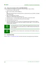
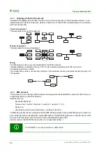
5.3.1 Commissioning of the ISOMETER® iso1685FR
System = IT System ?
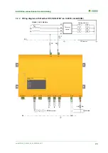
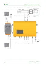
Device connection
U
n
< 400 V ?
U
N-PE
< 3 kV,
U
L1‘-PE
< 3kV ?
iso1685FR not suitable
No
Deenergize the installation before
connecting the device.
E and KE to PE
System to L1/+, L2/-
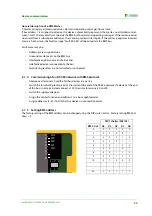
Optional device connection
BMS bus to A, B, S
Supply voltage to A1/A2
Signal peripherals at K1, K2, K3
11-12-14, 21-22-24, 31-32-34
Switch on supply voltage
Switch on mains voltage
No
Yes
ja
ja
iso1685FR not suitable
Connection fault or device error:
check the connections
Should factory settings
be kept?
No
Make the settings via the
BMS bus
Are the alarm LEDs
lighting?
No
Yes
The set response value is too low
- adjustment required
Function test with a suitable
ohmic resistance between the
system and earth. Value:
50% of the response value Z
an
Yes
No
Check connections
Remove resistance
The iso1685FR is connected
correctly and is functional
Alarm LEDs no longer lighting?
Alarm relays switched?
No
The iso1685FR successfully
carries out a self test
ja
No
ja
Are the alarm LEDs lighting?
Alarm relays switched?
Summary of Contents for ISOMETER iso1685FR
Page 6: ...6 ...
Page 10: ...Important information 10 iso1685FR M _D00002_02_M_XXEN 06 2017 ...
Page 14: ...Safety instructions 14 iso1685FR M _D00002_02_M_XXEN 06 2017 ...
Page 42: ...Diagram for the calculation of Ze 42 iso1685FR M _D00002_02_M_XXEN 06 2017 ...
Page 44: ...Information about the measuring method 44 iso1685FR M _D00002_02_M_XXEN 06 2017 ...
Page 50: ...INDEX 50 iso1685FR M _D00002_02_M_XXEN 06 2017 ...
Page 51: ...INDEX 51 iso1685FR M _D00002_02_M_XXEN 06 2017 ...


