


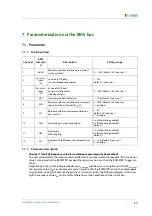


Parameterization via the BMS bus
38
iso1685FR(M)_D00002_02_M_XXEN/06.2017
•
Channel 2 (C
e-Anlage/
nF) and channel 3 (R
e-Anlage
/kΩ): Insulation parameters during commissioning:
When the device is operated, the insulation condition of the installation can be stored as "good condi-
tion" via these two parameters.
•
Channel 4 (MPT) Measured data buffer size
This parameter defines the buffer size for the measure-
ment results.The triggering time of the ISOMETER® depends linearly on the buffer size: A new measure-
ment is entered into the buffer every 20 ms. The advantage of a higher buffer depth is that the
insulation level of the system can be determined more reliably.The disadvantage is that the reaction
time is extended.The larger the buffer size is set, the longer it takes for the mean value of the buffer ent-
ries to fall below the threshold value. A tripping time of 150 ms, as specified in the technical data,
applies to a maximum buffer size of 4 (factory setting).
•
Channel 5 (FAN) Step-wise readjustment of the sampling frequency:
Service parameters.
•
Kanal 6 (CCN) Parameters for coupling monitoring of the N-conductor connection:
Service parameters.
•
Kanal 7 (CCN) Parameters for coupling monitoring of the L-conductor connection:
Service parameters.
•
Channel 8 (EWL –
U
an
/
V
): Response offset voltage
U
N-PE
(passive method)
This parameter defines the response threshold for the passive measurement method. In the case of
unsymmetric insulation faults on one or more phases, an offset voltage develops between the star
point of the IT network and earth.If the offset voltage
U
N-PE
exceeds the set response value
U
an
, the
ISOMETER® triggers an alarm.
•
Channel 9 (SFL): Measurement suppression response value (Interference detection active
method)
Interference detection is implemented for the active measuring method in order to prevent incorrect
measurements and therefore avoid false alarms.Active method interferences happen, for example,
because of spontaneous voltage spikes or voltage pulses in the network being monitored.The
ISOMETER® compares the voltage profile of successive network periods and discards the current deter-
mined measured value if the difference of the voltage profile considered exceeds the set response
value.
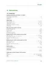
10
100
1.000
10
20
30
40
50
60
70
80
90
100
110
120
130
140
150
160
170
180
190
200
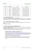
Z
an-max
in Abhängigkeit der System-Ableitkapazität
>100M
300k
200k
100k
Z
an
/kΩ
C
e-Anlage
/nF
Beispiel:
Bei einer System-Ableitkapazität C
e-Anlage
von 50nF, darf der
Ansprechwert Z
an
maximal auf 100kΩ eingestellt werden.
(Annahme: System-Isolationsfehler R
e-Anlage
> 100MΩ)
R
e-Anlage
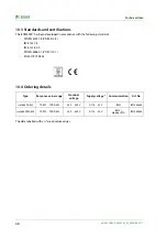
Summary of Contents for ISOMETER iso1685FR
Page 6: ...6 ...
Page 10: ...Important information 10 iso1685FR M _D00002_02_M_XXEN 06 2017 ...
Page 14: ...Safety instructions 14 iso1685FR M _D00002_02_M_XXEN 06 2017 ...
Page 42: ...Diagram for the calculation of Ze 42 iso1685FR M _D00002_02_M_XXEN 06 2017 ...
Page 44: ...Information about the measuring method 44 iso1685FR M _D00002_02_M_XXEN 06 2017 ...
Page 50: ...INDEX 50 iso1685FR M _D00002_02_M_XXEN 06 2017 ...
Page 51: ...INDEX 51 iso1685FR M _D00002_02_M_XXEN 06 2017 ...


