


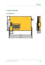


Device overview
20
iso1685FR(M)_D00002_02_M_XXEN/06.2017
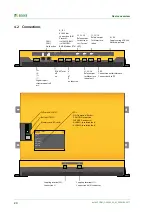
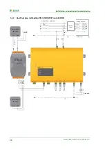
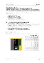
4.2 Connections
A1 A2
E KE
21 22 24
31 32 34
k l kT IT
A B S
RS-485
Term.
off on
CAN 1
CAN 2
I2+ I2- I1+ I1-
K3
K2
11 12 14
K1
I2+ I2- I1+ I1-
A B S
k I kT IT
31 32 34
21 22 24
11 12 14
E KE
A1 A2
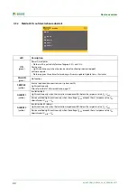
I2+
I2-
I1+
I1-
Digital input 1
starts manual self
est
RS-485 Term.
off
on
CAN 1
CAN 2
No function
A, B, S
RS-485 bus
connection (A,B)
Protocol:
iso1685FR: BMS
iso1685FRM:
BMS, Modbus RTU
k
I
kT
IT
no function
31, 32, 34
Relay output
for device er-
ror ("Service“
LED)
21, 22, 24
Relay output
for Alarm insu-
lation fault
11, 12, 14
Relaiy output
for Alarm insu-
lation
E, KE
Connection earth/reference.
Connect both to PE
A1, A2
Supply voltage DC24V.
Abritrary polarity
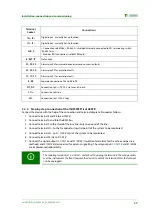
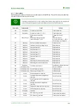
SERVICE
ALARM 2
ISOMETER
®
iso1685
ON
ALARM 1
PGH ON
LEDs:
- ON: Operation (flashes)
- PGH ON: No function
- SERVICE: Device error
- ALARM 1: Insulation fault
- ALARM 2: Insulation fault
DIP switch (SS8103)
Button (ST6101)
Memory card (SD card)
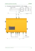
L2/L-
L1/L+
L1/+ L2/-
Coupling terminal L2/-.
Connection L1‘
Coupling terminal L1/+.
Connection (to) N conductor
Summary of Contents for ISOMETER iso1685FR
Page 6: ...6 ...
Page 10: ...Important information 10 iso1685FR M _D00002_02_M_XXEN 06 2017 ...
Page 14: ...Safety instructions 14 iso1685FR M _D00002_02_M_XXEN 06 2017 ...
Page 42: ...Diagram for the calculation of Ze 42 iso1685FR M _D00002_02_M_XXEN 06 2017 ...
Page 44: ...Information about the measuring method 44 iso1685FR M _D00002_02_M_XXEN 06 2017 ...
Page 50: ...INDEX 50 iso1685FR M _D00002_02_M_XXEN 06 2017 ...
Page 51: ...INDEX 51 iso1685FR M _D00002_02_M_XXEN 06 2017 ...


