


31
iso1685FR(M)_D00002_02_M_XXEN/06.2017
6. Device communication
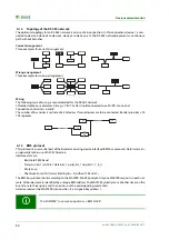
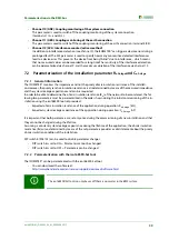
6.1 Device communication via the BMS bus
6.1.1 RS-485 interface with BMS protocol
The RS-485 interface, galvanically isolated from the device electronics, serves as a physical transmission medi-
um for the BMS protocol (Bender measuring device interface). When one device or other bus-capable devices
are interconnected via the BMS bus in a network, the BMS bus must be terminated at both ends with a 120 Ω
resistor. For this purpose, the device is equipped with the terminating switch RS-485 Term. (off/on).
An RS-485 network that is not terminated is likely to become unstable and may result in malfunctions. Only the
first and last device in one line may be terminated. Stub feeders in the network (if any) must not be terminated.
The length of the stub feeders is restricted to 1 meter.
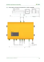
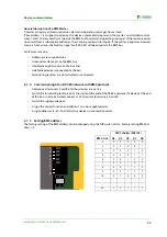
Abb. 6.1: Wiring and termination of the BMS bus with the device housing
A1 A2
E KE
21 22 24
31 32 34
k l kT IT
A B S
RS-485
Term.
off on
CAN 1
CAN 2
I2+ I2- I1+ I1-
K3
K2
11 12 14
K1
I2+ I2- I1+ I1-
A B S
k I kT IT
31 32 34
21 22 24
11 12 14
E KE
A1 A2
A B S
RS-485
Term.
off on
CAN 2
A B S
A B S
CAN 2
A B S
maximum length of the RS-485 network: 1200 m
1. device
… device
last device
stub feeder
max. 1 m
Summary of Contents for ISOMETER iso1685FR
Page 6: ...6 ...
Page 10: ...Important information 10 iso1685FR M _D00002_02_M_XXEN 06 2017 ...
Page 14: ...Safety instructions 14 iso1685FR M _D00002_02_M_XXEN 06 2017 ...
Page 42: ...Diagram for the calculation of Ze 42 iso1685FR M _D00002_02_M_XXEN 06 2017 ...
Page 44: ...Information about the measuring method 44 iso1685FR M _D00002_02_M_XXEN 06 2017 ...
Page 50: ...INDEX 50 iso1685FR M _D00002_02_M_XXEN 06 2017 ...
Page 51: ...INDEX 51 iso1685FR M _D00002_02_M_XXEN 06 2017 ...


