Bender ATICS-2-63A-ISO Manual Download Page 53


ATICS-2-ISO_D00046_04_M_XXEN / 03.2021 53

ATICS-2-63A-ISO

Menu item

Function

Page

1. IT system

Test of the integrated insulation monitoring device (insulation resistance, 
load in %, overtemperature)

P. 54

2. Autom. changeover

Test of the changeover function. Switches back automatically after time 
t(test).

P. 54

3. Manual changeover

Test of the changeover function. Switches back after pressing the "RE-
SET" button.

P. 55

4. Last switch

Save last changeover as test

P. 55

5. Generator

Start generator without switching over. Terminate test by pressing the 
"RESET" button.

P. 56

6. Test communication

Communication test via the BMS bus. To do this, simulate an alarm and 
send an alarm message via the BMS bus.

P. 57


i

Test menus 2…4 are protected by a password (see chapter „Settings menu 11: Password“ on p. 
79). Password protection is only effective if the password has been enabled. When an attempt is 
made to open one of these menus, the password entry screen appears automatically: 


i

During an "Autom. changeover" test or "Manual changeover" test, changeover does not take place 
until a delay time has elapsed which is indicated by the progress bar. 
For technical reasons, the menu items "Control> Test > Manual changeover", "Control > Test 
>Generator" and "Control > Test > Communication" cannot be accessed via gateway (COM465…, 
CP700, …).


i

If manual mode is selected for changeover (transparent cover open or digital input set to "manual 
changeover"), no changeover can take place at the test menu "Autom. changeover" or "Manual 
changeover". ATICS® then displays the following message:


i

To run a test, the transfer switching and monitoring device must be in automatic mode.


i

During an "Autom. changeover" or "Manual changeover" test, the changeover period t(1->2) is di-
splayed. This is the time required for switching over from the preferred line to the redundant line. 
This time may differ from the return transfer time! See chapter „Time diagram: Changeover between 
preferred and redundant line“ on p. 19 .
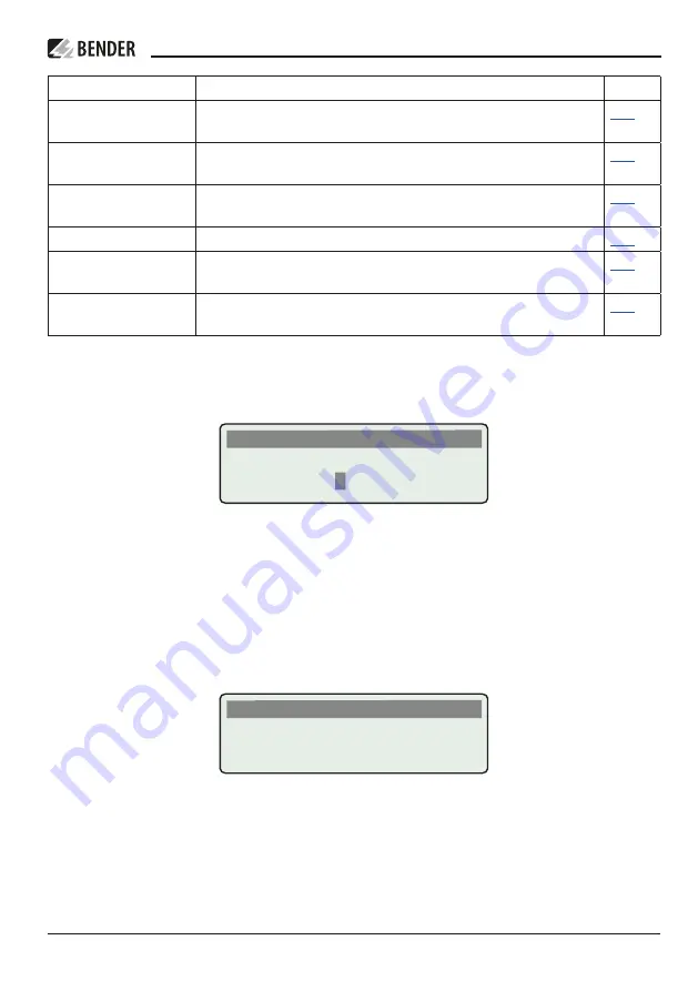
TEST

Enter password: 

0  0  0

Info

TEST

Cancel

Summary of Contents for ATICS-2-63A-ISO

Page 1: ...SO_D00046_04_M_XXEN 03 2021 ATICS 2 63A ISO ATICS 2 80A ISO Automatic transfer switching devices with monitoring functions for unearthed safety power supplies Software version D333 V1 3x D334 V1 3x D3...

Page 2: ...3 cents 30 sec remaining time 6 3 cents min Mobile phone higher depending on mobile phone tariff Repair service Repair calibration and replacement service Londorfer Strasse 65 35305 Gr nberg Germany...

Page 3: ...scription 13 3 1 2 Changeover 13 3 1 3 IT system unearthed power supply 13 3 1 4 Messages 13 3 1 5 Other functions 13 3 2 Functional safety 14 3 2 1 Product life cycle management 14 3 3 Application ex...

Page 4: ...tions for connection 42 4 2 9 1 Transformers for the IT system 42 4 2 9 2 Temperature sensors 42 4 2 9 3 BMS bus 42 4 2 9 4 MK alarm indicator and test combination TM alarm indicator and operator pane...

Page 5: ...et menu 3 Changeover 59 6 2 4 4 Reset menu 4 Service alarm 60 7 Menu mode Operation and setting 61 7 1 Switching on and calling up the main menu 61 7 2 Menu overview diagram 62 7 3 Function of the mai...

Page 6: ...on and service 89 9 1 Periodic verification 89 9 2 Maintenance 90 9 3 Cleaning 90 9 4 Operation with bypass switch 90 9 5 Replacing the ATICS 91 9 5 1 Removing the existing ATICS 92 9 5 2 Installing a...

Page 7: ...edium risk of danger that can lead to death or serious injury if not avoi ded I Caution Indicates a low level risk that can result in minor or moderate injury or damage to pro perty if not avoided i I...

Page 8: ...recommended by Bender Catastrophes caused by external influences and force majeure Mounting and installation with device combinations not recommended by the manufacturer This operating manual and the...

Page 9: ...shock and injury Reference signs must always be clearly legible Replace damaged or illegible signs immedi ately Make sure that the dimensions of the BSV battery supported safety power supply the gen...

Page 10: ...10 ATICS 2 ISO_D00046_04_M_XXEN 03 2021 Intended use...

Page 11: ...pen to the public DIN VDE 0100 718 Emergency power supplies Heating air conditioning ventilation cooling EDP data centres Fire extinguisher and sprinkler systems Several versions of the ATICS are avai...

Page 12: ...12 ATICS 2 ISO_D00046_04_M_XXEN 03 2021 System description...

Page 13: ...he preferred supply or when the values are outside the permissible voltage range Voltage monitoring line 1 2 input and line 3 output Automatic return to the preferred line on voltage recovery Monitori...

Page 14: ...nformation refer to Chapter Commissioning settings and testing on p 45 chapter Periodic verification and service on p 89 3 3 Application examples 3 3 1 Application example operating theatre ATICS 2 63...

Page 15: ...second supply line 2 Voltage monitoring at the automatic transfer switching device output line 3 Monitoring of the changeover switch for correct switch position Internal functional testing including...

Page 16: ...ansfer delay time t 2 1 has elapsed and no switch back lock is enabled or immediately after pressing the RESET button or when the redundant line fails even when the switch back lock is enabled the set...

Page 17: ...st not continually change back and forth between the two lines This can occur if the short circuit current is small and the automatic transfer switching device switches faster than the short circuit b...

Page 18: ...e line 1 Alarm failure line 2 Switch position Time delay t pulse Pulse time 15 30 ms t 0 Dead time t on 1 Response delay ALARM failure voltage line 1 Measuring time approx 50 ms t off 1 Delay on relea...

Page 19: ...ATICS 2 ISO_D00046_04_M_XXEN 03 2021 19 ATICS 2 63A ISO tion with delay on release Switching back to line 1 if line 2 has failed mp t 0 t Imp 0 1 t off 1 t Imp t 0 t Imp 2 0 1 t 2 1 t on 2 2...

Page 20: ...ime t start Example Line 1 is set as the preferred line Optional Staggered switching after complete power failure Optional Staggered switching after complete power failure Voltage line 1 Voltage line...

Page 21: ...ATICS 2 ISO_D00046_04_M_XXEN 03 2021 21 ATICS 2 63A ISO...

Page 22: ...n delay after complete power failure and restart of the ATICS t off 1 Delay on release ALARM failure voltage line 1 t off 2 Delay on release ALARM failure voltage line 2 t 2 1 Return transfer delay ti...

Page 23: ...50 ms Measuring time approx 50 ms Measuring time approx 50 ms 2 is suppressed until then t Imp t 0 t Imp 0 1 t GenOff After switching on the ATICS performs a quick measurement of the voltage with t of...

Page 24: ...ender devices such as an alarm indicator and test combination via the BMS bus Locating current injector When an insulation fault is detected in an IT system the integrated locating current injector ge...

Page 25: ...ry 3 5 4 Power supply The coils of the changeover switch are each supplied from the line which is not currently switched on This ensures that it is possible to switch to the redundant line if the pref...

Page 26: ...device only for ES version Connection for supply voltages only for 400 version 5 Manual mode of the device indicates the switch position 6 Allen key for manual mode 7 Transparent cover for changeover...

Page 27: ...en disconnected Observe the rules for working on electrical installations i Disturbance due to loud switching noise Install the ATICS in a closed electrical operating area or in a sound proof distribu...

Page 28: ...e the ATICS A B N N N N N 1 Push back the locking hook B in the middle of the top and bottom terminal cover A by using a screwdriver 2 Remove the terminal cover D C N 1 Place the ATICS on the top edge...

Page 29: ...transformer supply line from the transfer switching device and the transformer outgoing line to the next distribution board section should be installed short circuit and earth fault proof Halogen fre...

Page 30: ...peration al current of the transformer Refer to the technical specifications of the ATICS for the maximum size of back up fuses F1 or F2 Selecting a fuse for several loads This circuit branches into s...

Page 31: ...nnec ted to the device from the top Use a torque wrench to tighten the terminal screws Check all the screws on a regular basis to make sure they are seated tightly I Danger Caution when operating the...

Page 32: ...ital input configurable see chapter Settings menu 6 Dig input on p 74 NC Not used L1 IT L2 IT Connection to the IT system Monitoring the insulation resistance If an insulation fault exists Feeding of...

Page 33: ...4 2 3 ATICS basic configuration I Warning Risk of destruction if connected incorrectly The terminals marked with are intended for Bender internal purposes only If this is ignored the ATICS automatic...

Page 34: ...connected incorrectly The terminals marked with are intended for Bender internal purposes only If this is ignored the ATICS automatic transfer switching and monitoring device may be damaged An diese K...

Page 35: ...f connected incorrectly The terminals marked with are intended for Bender internal purposes only If this is ignored the ATICS automatic transfer switching and monitoring device may be damaged An diese...

Page 36: ...uction if connected incorrectly The terminals marked with are intended for Bender internal purposes only If this is ignored the ATICS automatic transfer switching and monitoring device may be damaged...

Page 37: ...2021 37 ATICS 2 63A ISO I Risk of ineffective voltage monitoring The ATICS must be supplied with power directly from the connected line not from another phase as shown If this is not observed the volt...

Page 38: ...in the connection example I Warning Risk of destruction if connected incorrectly The terminals marked with are intended for Bender internal purposes only If this is ignored the ATICS automatic transfe...

Page 39: ...63A ISO I Risk of ineffective voltage monitoring The ATICS must be supplied with power directly from the connected line not from another phase as shown If this is not observed the voltage monitoring...

Page 40: ...orrectly The terminals marked with are intended for Bender internal purposes only If this is ignored the ATICS automatic transfer switching and monitoring device may be damaged Power supply for the AT...

Page 41: ...ATICS 2 ISO_D00046_04_M_XXEN 03 2021 41 ATICS 2 63A ISO...

Page 42: ...ntrol Panel MK2430 MK800 CP9xx and TM800 are used They have the following tasks Display alarms from the ATICS transfer switching device Mutual monitoring for failure Test of the ATICS functions start...

Page 43: ...and do not use ferrules Use a Torx screwdriver T20 or a slotted screwdriver of 6 5 x 1 2 mm Tightening torque 2 5 Nm 25 mm or 4 5 Nm 25 mm Ensure that the lines are short circuit and earth fault proof...

Page 44: ...splay Only then can the Allen key be used to set the changeover switch to manual mode Enabling manual mode Variant A Open the transparent cover Set the digital input M A function must be set see chapt...

Page 45: ...s for MK alarm indicator and test combinations or TM alarm indicator and operator panels or CP9xx These panels display messages from the ATICS automatic transfer switching and monitoring device and mo...

Page 46: ...he EDS channels if available are to be displayed with circuit and or room name 5 1 2 ATICS messages on the BMS bus channel use BMS chan nel Entry in the menu 1 Alarm meas values Description Operating...

Page 47: ...hangeover period of the last test Changeover period 7 7 TEST dd mm yy Next TEST due on date Date when due 8 8 Service dd mm yy Next service due on date Date when due Messages for alarm on the digital...

Page 48: ...f the automatic transfer switching device Setting Response delay t on If several transfer switching devices are connected in series in a power supply system it is rec ommended that they be time graded...

Page 49: ...ating resistors cause malfunction and must not be used Please note the information in the BMS bus manual An automatic transfer switching and monitoring device with an MK and a TM Device Parameter Addr...

Page 50: ...r Address settings ATICS for area A Bus address 3 First MK Central monitor ing Address 1 Test address 3 6 Alarm address 2 3 4 5 6 Second MK for area A Address 2 Test address 3 Alarm address 1 3 4 EDS1...

Page 51: ...and error messages disable switch back lock change parameters scroll MENU Toggle between standard display alarm display and MENU confirm parameter changes 6 2 Quick reference guide 6 2 1 Display under...

Page 52: ...7 If individual alarm messages are programmed on a TM alarm indicator and operator panel or a CP9xx or an MK alarm indicator and test combination the display of this device may differ from the display...

Page 53: ...e of these menus the password entry screen appears automatically i During an Autom changeover test or Manual changeover test changeover does not take place until a delay time has elapsed which is indi...

Page 54: ...enu 2 Autom changeover Autom changeover Test of the changeover function The device switches to the redundant line The changeover period t 1 2 is displayed After the set time t test has elapsed the dev...

Page 55: ...the ATICS remains in this switch position and in TEST mode Wait until Quit RESET appears on the display Press the RESET button Check whether the ATICS has switched to the preferred line i Manual mode...

Page 56: ...tests required a Line 1 off then line 2 off ATICS must switch to position 0 b Line 2 off then line 1 off ATICS must switch to position 0 c Automatic test with both lines available 6 2 3 6 Test menu 5...

Page 57: ...ck that these devices are responding to the alarm message as requested Select a channel 1 Use the arrow button to go to the channel settings Press the button 2 Use the arrow buttons to select the chan...

Page 58: ...larm value for the Maximum number of changeover operations performed Maximum number of operating hours Maximum number of changeover operations performed which were carried out with overcurrent or shor...

Page 59: ...easing service life the probability of component failure increases for every technical product For operation according to IEC 61508 2 additional limit values are monitored number of switching cycles o...

Page 60: ...successful test of the changeover process is carried out 7 Changeover I 0 Number of changeovers performed which were carried out with overcurrent of short circuit current see chapter Menu 2 Changeove...

Page 61: ...d If there are no messages pending the standard display will appear after the start Press the MENU button to open the main menu The following buttons can be used in the main menu Select menu items Con...

Page 62: ...the menus Exit 1 Alarm meas values 3 History Logger 5 Control 2 Changeover 6 Digital Input 7 Info 1 Changeover Exit 2 Voltage 3 Current 4 IT system 5 Relay 6 Digital Input 7 Data logger 8 Language 9...

Page 63: ...m no alarm alarm Menu Description Exit Exit Alarm meas values menu go up one menu level 1 Line 1 228V Line 1 Measured value mains voltage 2 Line 2 183V Line 2 Measured value mains voltage 3 Position 1...

Page 64: ...nabled 16 I 3 5A Load current TN system 17 Dig input Alarm dig input channel disabled i All messages except measured value frequency are also present on the BMS bus see chapter Messages with error cod...

Page 65: ...tor panel or an MK alarm indicator and test combination 2 Data logger Displays the history of measured values supply line 1 supply line 2 switch posi tion of the transfer switching device load current...

Page 66: ...3 2 Operating example Config logger 1 Use the arrow buttons to select the re quired entry In this case The settings for the digital input are changed here 2 Press to call up the additional text for th...

Page 67: ...est via the interface P 77 10 Clock Set the date and time on the real time clock on this device The time setting is synchronised via the BMS bus The device with address 1 e g MK2430 MK800 TM alarm ind...

Page 68: ...supply Safety power supply The setting also influences the creation of the alarm text which is displayed in case of voltage failure on a line Setting alarm text U1 U2 Undervoltage overvoltage voltage...

Page 69: ...0 s 100 s only active when System Line G Resolution of setting 1 s 5 s 14 t Gen off Time delay for turning off the generator after switching back to the preferred line Setting range 2 s 180 min only a...

Page 70: ...ange 240 275 V 417 V 478 V 3 t on Response delay Setting range 50 ms 100 s Resolution of settings 50 ms 100 ms 1 s 5 s 10 s 4 t off Delay on release Setting range 200 ms 100 s Resolution of settings 5...

Page 71: ...Insulation Setting range 50 250 k Resolution of setting starting at 5 k 2 Current trans former Measuring current transformer T4 in the connection example P 33 STW2 Measuring current transformer STW3 M...

Page 72: ...n can be set for the relay as follows Alarm message Active Generator Start If Alarm is set and then Line 1 on is selected the relay switches if line 1 fails If Active is set and then Line 1 on is sele...

Page 73: ...t of an alarm N C operation Relay only switches in the event of an alarm N O T operation Relay switches in the event of an alarm or a test N C T operation Relay switches in the event of an alarm or a...

Page 74: ...solated It is designed for an input of AC DC 24 V ATICS 2 ISO has a digital input and a relay output with a changeover contact For the input selection is possible when the input is set to 24V high or...

Page 75: ...Changes the preferred line TEST A test changeover is carried out In generator mode the genera tor start relay is also switched The test is completed when the output is reset ALARM Generates a Digital...

Page 76: ...er one year If changes are saved every minute the service life is increa sed to approx 57 years Select the settings in the Datalogger Modific settings menu in a way that frequent saving over longer pe...

Page 77: ...ched the current measured value overwrites the oldest entry no Once the maximum number of measured values which can be saved has been reached no further measured values are saved 3 Delete Delete Clear...

Page 78: ...e device without BMS master I Danger When this setting is selected the conditions for functional sa fety SIL2 are no longer met I Warning No EDS functionality is possible if this settings has been sel...

Page 79: ...g the time hours and minutes 7 3 4 11 Settings menu 11 Password The device has two separate passwords for the Settings menu and the TEST menu Menu Description Exit Exit settings menu Password go up on...

Page 80: ...up one menu level 1 Password Change the password for the TEST menu Setting range 000 999 Resolution of setting 1 2 Status Enable or disable the password protection for the TEST menu on Password prote...

Page 81: ...Whether the input is set to 0 V or 24 V depends on the set response value see chapter P 74 7 3 7 Menu 7 Info This menu displays information about the device and the software Press the arrow button sev...

Page 82: ...82 ATICS 2 ISO_D00046_04_M_XXEN 03 2021 Troubleshooting...

Page 83: ...insulation fault Eliminate fault in the system Overload Current consumption too high Sporadic indication of load current chang ing without any apparent reason The fault can also be caused by an imperm...

Page 84: ...ected Measuring current transformer STW3 channel 7 Check connecting wire of measuring current transformer No master There is no device with master function or back up master device with address 1 avai...

Page 85: ...e chapter Reset menu 3 Changeover on p 59 3 13 Changeover due to overcurrent or short circuit detected These changeovers reduce the life of the device Currents exceeding 130 A are considered to be ove...

Page 86: ...uring changeover process Occurs when the voltage on the new line fails dur ing the changeover Also occurs when the test set ups do not supply sufficient current for switching the coils of the ATICS Ca...

Page 87: ...o regular testing Connection faults are recognised during the self test Self tests are carried out After switching the ATICS power supply on After each changeover process When the TEST IT system funct...

Page 88: ...2 changeover operations The time delay is required to cool the system Why does writing back reports backups lead to error messages ATICS like many Bender devices can be monitored and configured by mea...

Page 89: ...trical installations and stationary equipment in Special installations or locations DIN VDE 0100 Group 700 1 year According to TRBS1203 the tests must be carried out by a qualified person The person c...

Page 90: ...ews on the ATICS and the Torx screws of the connectors on the incoming and out going lines of the automatic transfer switching device to make sure they are tight 9 3 Cleaning ATICS may only be cleaned...

Page 91: ...2 Conditions for operation with the bypass switch Wiring must be carried out according to Connection example ATICS with bypass switch on p 34 The following must bet set in Settings menu 6 Dig input 1...

Page 92: ...existing ATICS to manual operation switch to position 0 and secure against unintentional switch on see chapter Connecting the ATICS safely on p 31 3 Remove connections 4 Remove the ATICS Undo the mou...

Page 93: ...covers A by using a screw driver to push back the locking hook B located approximately in the middle of the cover in each case Use a screwdriver to pull the lower yellow slide lock C down wards and r...

Page 94: ...the cover in each case Undo the Allen screws of the terminals C Remove the green plug connectors D at top and bottom Remove the black bridge E at the bottom Undo the mounting screws and remove the ATI...

Page 95: ...on p 99 Short circuit current Icc and fuses see table Utilisation categories acc to DIN EN 60947 on p 99 Voltage monitoring changeover Frequency range fn 40 70 Hz Undervoltage response value Alarm 1...

Page 96: ...er Measuring current transformers STW2 STW3 SWL 100 A Measuring range IL TRMS 10 110 of the response value Adjustable response value STW2 STW3 SWL 100A 5 50 100 A 1 A steps Relative uncertainty 5 Cres...

Page 97: ...djustable function see Settings menu 5 Relay on p 71 Electrical endurance under rated operating conditions number of cycles 10 000 Contact data according to IEC 61810 Rated operational current AC resi...

Page 98: ...que Torx screwdriver T20 or slotted screwdriver 6 5 x 1 2 mm 2 5 Nm 25 mm 4 5 Nm 25 mm Torque setting for manual operation hexagon socket 5 mm approx 6 Nm Electronics Connection pluggable screw type t...

Page 99: ...ated as conditional short circuit with circuit breaker that ensures tripping in less than 0 3 s Current rated as short time withstand Icw 0 3 s kA eff 7 7 Short circuit operation single switch Current...

Page 100: ...100 ATICS 2 ISO_D00046_04_M_XXEN 03 2021 Technical data 10 2 T V test report according to VDE 0100 Part 710...

Page 101: ...ATICS 2 ISO_D00046_04_M_XXEN 03 2021 101 ATICS 2 63A ISO 10 3 T V certificate regarding functional safety...

Page 102: ...DIN EN 61558 1 VDE 0570 1 2006 07 DIN EN 61558 1 Amendment 1 VDE 0570 1 Amendment 1 2008 11 DIN EN 61558 1 Amendment 2 VDE 0570 1 Amendment 2 2008 12 DIN EN 61558 1 A1 VDE 0570 1 A1 2009 11 The stand...

Page 103: ...0009 AN412 Power supply unit DC 12V for ATICS ES energy storage device B924150 Description ATICS 2 ISO 2 pole transfer switching and monitoring device with integrated insulation load and temperature m...

Page 104: ...of the publisher Bender GmbH Co KG PO Box 1161 35301 Gr nberg Germany Londorfer Str 65 35305 Gr nberg Germany Tel 49 6401 807 0 Fax 49 6401 807 259 E mail info bender de www bender de ATICS 2 ISO_D000...

Reviews: