HCP-1801 HD/SD SDI Control Probe
Guide to Installation and Operation
HCP-1801
Page 9 of 27
When you click on one of these, you will change the
contents of sections 2 and 3.
•
Select a topic area by clicking on it
•
The selected topic is highlighted
Note that the icon representing the current input format (i.e.
525, 625, 1080i or 720p) in the topic area list is colored,
with the color indicating its status.
NB – selecting a topic area in this tree does
not
change
the input format selection
Section 2
. This section contains a list of parameters
associated with the topic selected in section 1.
•
Select one by clicking on it
•
The selected parameter is highlighted
Section 3.
This area contains all the controls and
adjustments for the topic area and parameter selected in
sections 1 and 2.
A complete description for all of these is given below.
In most cases, controls are provided in section 3 to
configure the probe’s features. Types of controls that may
be found are:
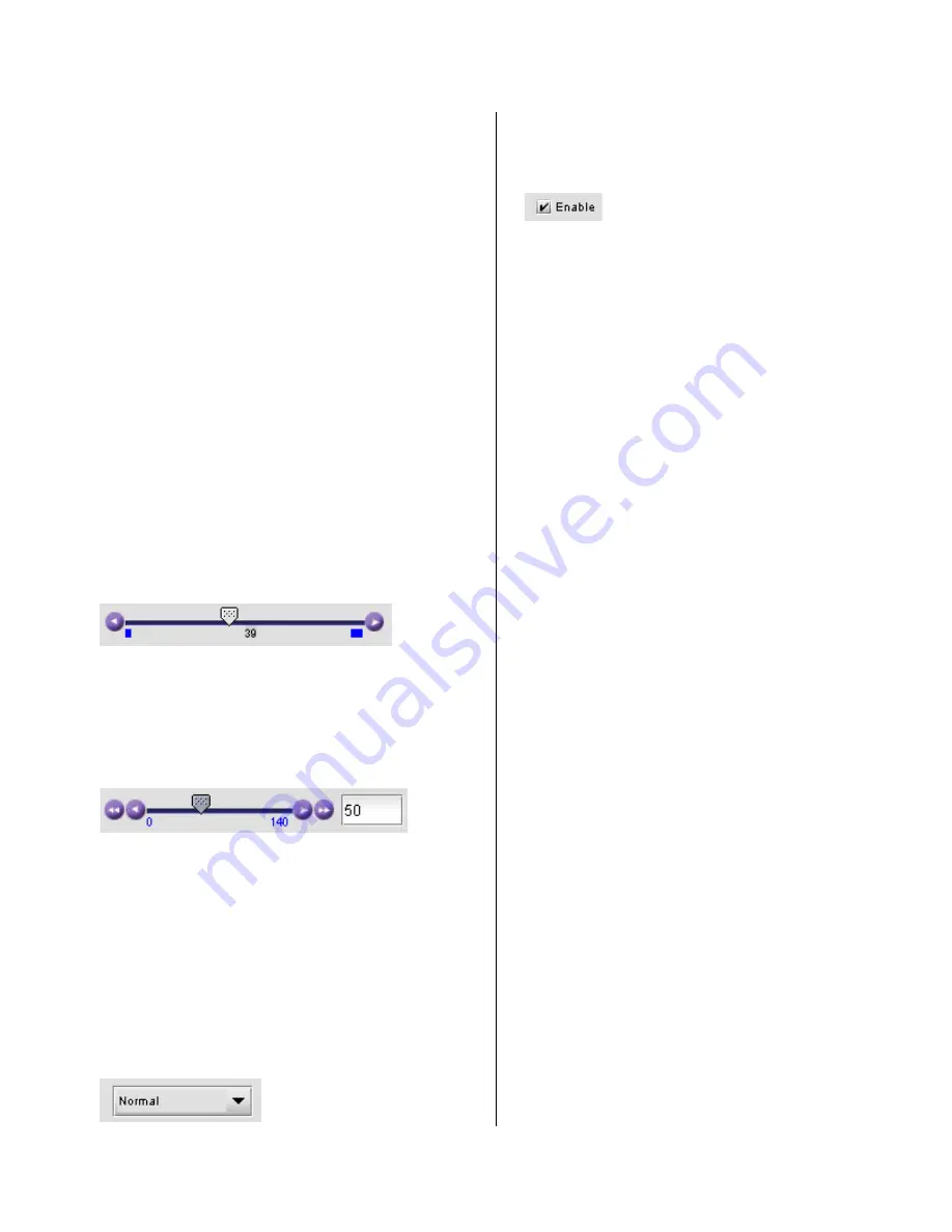
Slider:
The current value is displayed beneath the center of the
slider bar (e.g. 39 in the example shown). To change the
value
•
move the slider by clicking and dragging it
•
move the slider by clicking the arrow icon at either end
Slider with data box:
The current value is displayed in the data box at the right
hand side (e.g. 50 in the example shown). To change the
value:
•
move the slider by clicking and dragging it
•
move the slider by clicking the arrow or double-arrow
icon at either end
•
type a new value directly into the data box, and hit
“enter” from your keyboard. If you enter a value
outside the permitted range (as shown beneath the
slider), the data box will flash red and the value will not
be changed.
Pull-down list:
The current selection is shown on the icon. To change it,
click on the down arrow at the right of the box, and click on
the desired option in the list that appears below the box.
Check box (with label):
A selected box has a checkmark in it, as shown in the
example, while an unselected box is blank. Click on the
box to change its status.
Because the HCP-1801 is concerned with detecting the
presence of errors, much of its configuration involves
setting limits and thresholds against which the measured
parameter values will be compared. Many of the
adjustment panels contain similar elements, and these will
be described in detail here, to avoid considerable
repetition.
The parameter configuration pane usually includes, from
top to bottom:
•
Enable
: a checkbox to enable the alarm associated
with this parameter
•
Threshold:
a threshold value for detection of an error.
The error will be detected when the measured
parameter falls above (or below, depending on the
nature of the parameter) the indicated threshold value.
The values are those of the equivalent analog signal.
In most cases this is a slider with data entry box.
•
Conditions:
indicates the conditions under which a
detected error is flagged and reported.
◊
ERROR DURATION – the length of time during
which a parameter is allowed to be out-of-
tolerance without being identified as an error.
This is useful for situations such as a hard switch
or patch of a video signal where there is a
discontinuity in the signal which the user has
deliberately caused and does not need to be
flagged as an error. If a parameter is continuously
out of tolerance for the specified duration, then an
error is considered to have been detected.
However, this error will not be flagged (causing
the status LED to change color and an error
message to be sent out on the frame’s interface)
until the OCCURRENCE / DETECTION WINDOW
conditions have been satisfied.
(Range: 0 to 90 seconds)
◊
OCCURRENCE: the number of times that a
detected error is allowed to occur in a specified
DETECTION WINDOW before an error flag is set,
and the error is reported (status LED changes
color, and message sent on the interface)
(Range: 1 to 8 for video / 1 to 4 for audio)
◊
DETECTION WINDOW: the time interval during
which errors are counted to determine if the error
flag should be set. This is a moving window, e.g.


