HCP-1801 HD/SD SDI Control Probe
Guide to Installation and Operation
Page 4 of 27
HCP-1801
LUMA MIN ERROR
Indicates an average minimum
luminance error of the input video
signal
LUMA MAX ERROR
Indicates an average maximum
luminance error of the input video
signal
FREEZE ERROR
Indicates that a frozen image has
been detected on the input signal
BLACK ERROR
Indicates that a video black has
been detected on the input signal
OVERLOAD
Indicates a peak level error in one
or both channels
LEVEL MAX
Indicates an average maximum
level error in one or both channels
LEVEL MIN
Indicates an average minimum
level error in one or both channels
SILENCE
Indicates audio silence
in one or
both channels
DYNAMICS
Indicates lack of dynamics
in one
or both channels
SLICING
Indicates sounds with cuts
in one
or both channels
AUDIO PHASE
Indicates a phase error
STEREO WIDTH
Indicates a stereo width error
iCONTROL INTERFACE
The operation of the HCP-1801 is controlled using
Miranda’s iControl system. This manual describes the
control panels associated with the HCP-1801 and their use.
Please consult the iControl User’s Guide for information
about setting up and operating iControl.
In iControl Navigator or iControl Websites, double-click on
the HCP-1801 icon to open the control panel.
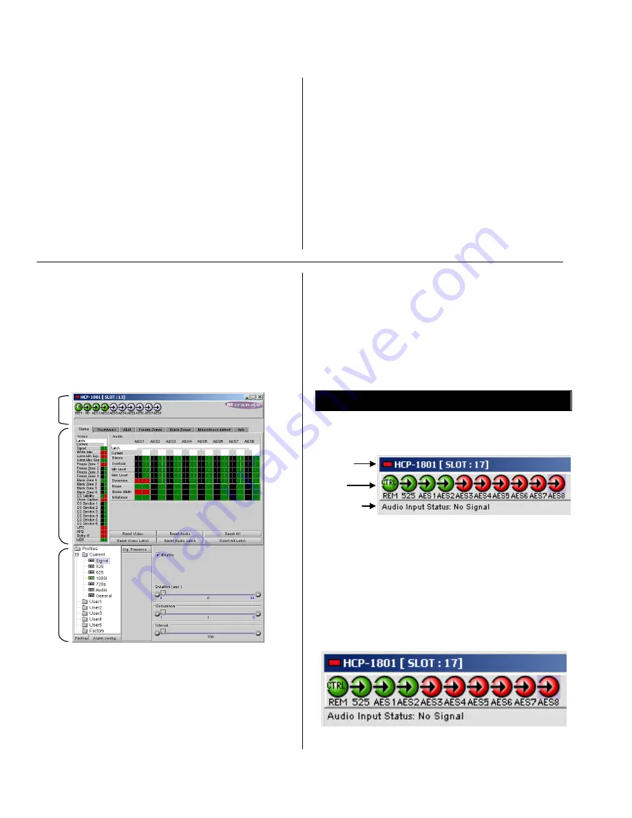
The control panel has three sections:
1. Card Status Area:
at the top of the panel, shows status
icons for several key items, and text messages describing
detected errors. A complete description of the Card Status
Area begins below
2. Display Area:
this area has seven tabs, each giving
access to a visual display of some aspect of the HCP-
1801`s operation. A complete description of these displays
begins on page 5.
3. Parameters Area:
gives access to all controls and
adjustments associated with this probe. A complete
description of the how to set up the probe using the
Parameters Area begins on page 8.
Card Status Area
The Card Status Area provides a continuous update of the
status of the HCP-1801. This area includes three sections:
Header
Icons
Message
area
The
header
gives the product name, and identifies the slot
in which it is installed in its Densité frame. At the left is a
status icon whose color shows the overall status of the
probe:
Green
= OK
Yellow = warning
Red
= error
The ten
Icons
monitor some specific aspects of the HCP-
1801’s operation:
(a)
(b)
(c)
(d)
(e) (f) (g) (h) (i) (j)
1
2
3


