BEKA Stream H Original Operating And Assembly Manual Download Page 21


 Page 

21 © 

BEKA 2019 All rights reserved!


...a product of

10.6 Delivery 

volume 

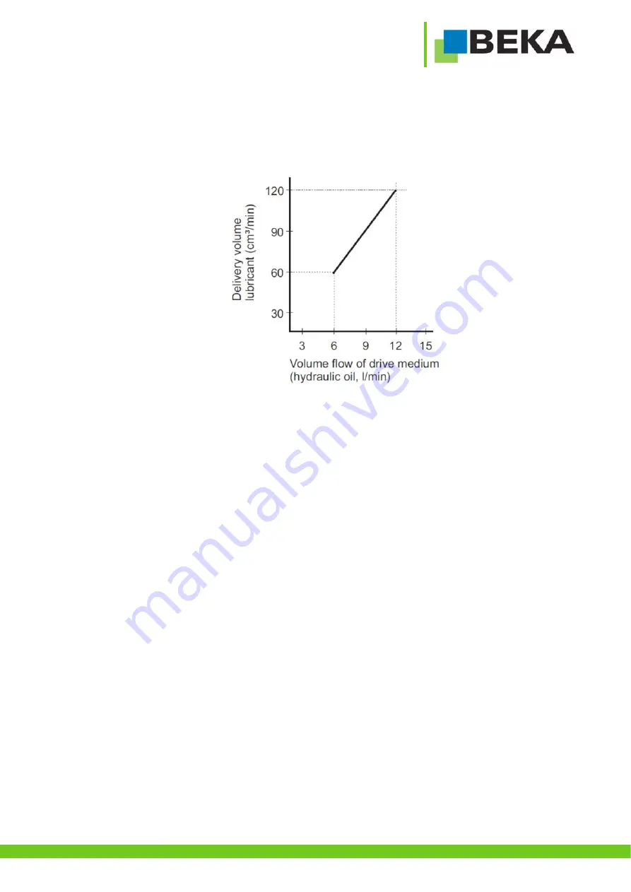
The device delivers a constant delivery volume of 120 cm³/min from a volume flow of the drive medium of 12 l/min (The volume flow 

of the drive medium is internally limited to max. 12 l/min). 
If the volume flow of the drive medium is lower, the volume flow changes as shown in the figure (fig. 23). 


Delivery volume depending on volume flow: 


Figure 23 

Summary of Contents for Stream H

Page 1: ...Page 1 BEKA 2019 All rights reserved a product of BAL2522_2523_Barrel_pump_Stream_H_0619EN Barrel pump BEKA Stream H Article no 2522 2523 Issue 06 2019 Original operating and assembly manual...

Page 2: ...p 13 8 2 Beka Stream H barrel version 13 8 3 Beka Stream H container version 13 9 Assembly instructions 14 9 1 Prefilling of return connection lubricant 14 9 2 Assembly of Beka Stream H barrel version...

Page 3: ...with accessories 37 20 Accessories 38 20 1 Filling zerk 38 20 2 Pressure limiting valve for progressive and dual line systems 38 20 3 Pressure limiting valve relief valve for single line system 38 20...

Page 4: ...250 bar Return pressure T max 43 psi 3 bar Volume flow of the drive medium 0 53 3 2 gal min 2 12 l min Purity class of the drive medium ISO 4406 21 19 16 1 2 Pump individually Weight max 21 3 kg 1 3 P...

Page 5: ...ved a product of BAL2522_2523_Barrel_pump_Stream_H_0619EN 2 Applicable documents Technical documentation of individual parts enclosed Level monitoring Please observe these documents for all work with...

Page 6: ...Page 6 BEKA 2019 All rights reserved a product of BAL2522_2523_Barrel_pump_Stream_H_0619EN...

Page 7: ...reserved a product of BAL2522_2523_Barrel_pump_Stream_H_0619EN 4 Versions Pump Pump container version Pump barrel version Symbol Symbol basis system Symbol single line system Figure 2 Figure 1 Figure...

Page 8: ...Page 8 BEKA 2019 All rights reserved a product of BAL2522_2523_Barrel_pump_Stream_H_0619EN Symbol hydro motor Figure 7...

Page 9: ...ol warns of hot surfaces Warning of suspended loads Warning of material damage due to electrostatic discharge Marks potential risks which may result in material damage if not avoided This heading is u...

Page 10: ...on Hazardous Substances in its latest version 5 5 Safety instructions for maintenance inspection and assembly All maintenance inspection and assembly work may only be carried out by qualified personne...

Page 11: ...rsons workplace and packing is well grounded when handling these devices 5 9 General hazard warning residual risk All components are designed according to valid regulations for the construction of tec...

Page 12: ...ning and authorization of your company to operate the device and to carry out the necessary work on the device Another use or a use beyond this scope is deemed improper 7 Scope of warranty Warranties...

Page 13: ...be lifted at the transport eyelets fig 9 red arrows In addition it must be fixed to the pump bracket so that it cannot tip over The device must only be transported when it is completely empty Observe...

Page 14: ...e should be protected against ambient and mechanic influences Ensure full access e g for filling with lubricant Special measures concerning noise prevention or oscillation reduction do not have to be...

Page 15: ...nipple is not included in the scope of delivery see chapter accessories Step 3 Fill the return connection G1 2 with a filling press until the lubricant escapes from the pump pipe figure 13 and 14 Step...

Page 16: ...the barrel Step 6 Tighten the wing screws fig 15 pos 4 until the cover fig 15 pos 3 is firmly fixed on the barrel Step 7 If available fold the tie rods optional accessory upwards and fix them with th...

Page 17: ...st be connected to thread P fig 17 pos P The connection line of the hydraulic return must be connected to thread T fig 17 pos T All components must be approved for the maximum operating pressure see c...

Page 18: ...mpare voltage details with the existing mains voltage Equipotential bonding must be done professionally by the operator via an according ground connection Connect the device according to the terminal...

Page 19: ...lubricant Use only greases with the same saponification Observe the safety data sheet of the lubricant manufacturer 10 2 Ventilation of the lubrication system Ventilate the whole lubrication system o...

Page 20: ...the filling connection G1 fig 22 pos 1 of the device Step 3 Fill the container with clean lubricant via the filling connection G1 fig 22 pos 1 until lubricant escapes from the ventilation screw fig 22...

Page 21: ...livery volume of 120 cm min from a volume flow of the drive medium of 12 l min The volume flow of the drive medium is internally limited to max 12 l min If the volume flow of the drive medium is lower...

Page 22: ...ricant is sucked back The integrated return connection on the pump can be used to return lubricant quantities from relief processes and pressure relief valves directly via the pump pipe into the lubri...

Page 23: ...ssure compensation that is caused by a varying level The ventilation filter element has to be checked at regular intervals and renewed if it is visibly polluted 11 3 3 Grease level dipstick If the gre...

Page 24: ...up Check all components for leakages and damage at least every four weeks If leakages are not repaired lubricant might escape under high pressure Remove possible puddles of lubricant immediately 12 2...

Page 25: ...fig 25 pos 1 hexagon socket AF 17 and connect a suitable filling pump at the filling connection G1 Step 2 Fill the device slowly with clean lubricant via the filling connection G1 fig 25 pos 1 until...

Page 26: ...rease barrel and press it into the new barrel Step 6 Now reinsert the pump pipe fig 26 pos 7 through the follower plate fig 26 pos 6 into the barrel Step 7 Push the pump fig 26 pos 1 with cover fig 26...

Page 27: ...t damaged or soiled Step 6 Remove lifting straps or chains from the pump and attach them to the new pump Step 7 Insert the new pump fig 27 pos 1 into the container or the barrel Carefully insert the p...

Page 28: ...urself are listed in the following Other repair works may only be done by BEKA 13 1 Exchange of pump element Step 1 Disassemble 4 cylinder screws A with an Allen key AF 6 figure 28 Step 2 Pull off pum...

Page 29: ...E reaches the lower final position figures 31 and 32 Step 5 Remove both lock screws F hexagon socket screw AF 4 and G hexagon socket screw AF 2 5 figure 33 one after the other Step 6 Unscrew the conv...

Page 30: ...ep 4 Step 8 Unscrew the conveyor pipe H via the hexagon AF10 at the suction piston E from the pump and remove it figures 37 and 38 Step 9 Unscrew the pump element K with an open ended wrench AF28 from...

Page 31: ...pletely figures 41 and 42 Step 11 Unscrew the pump element K via the hexagon AF10 at the suction piston E from the piston rod and remove it figure 43 Step 12 The pump element can be changed now and th...

Page 32: ...uct of 13 2 Exchange of motor Step 1 Disassemble motor fastening screws C with an Allen key AF 10 figure 44 Step 2 The motor D has to be lifted up now figure 44 Step 3 Reassemble new motor in reverse...

Page 33: ...at oil flows uncontrolled out of the pump housing O figure 46 Step 10 Remove the housing cover N and drain the oil in the pump housing figure 47 The oil is intended to be used for the entire life cycl...

Page 34: ...50 Step 13 Pull out the sealing bush R with a gripper from the connection body Q figure 51 Now the sealing kit can be replaced by a new one Step 14 Reassemble the device in reverse order All seals mus...

Page 35: ...s will be recycled They contain important raw materials 16 Troubleshooting Malfunction Possible cause Possible remedy Pump does not supply lubricant Barrel empty Exchange barrel Air inclusions in lubr...

Page 36: ...All rights reserved a product of 18 Dimensional drawing of pump without accessories Table for dimension L1 Container capacity l lbs L1 mm 41 60 494 54 90 640 68 120 786 Barrel capacity l lbs L1 mm 231...

Page 37: ...drawing of pump with accessories Container version Barrel version Container capacity l lbs H1 mm H2 mm H3 mm L mm D mm 41 60 449 560 884 504 437 54 90 595 706 1030 504 437 68 120 741 852 1176 504 437...

Page 38: ...Connection thread 2x G 1 2 Article number 10123881 A pressure limiting valve with an opening pressure of 240 bar is always built in for single line versions 20 3 Pressure limiting valve relief valve...

Page 39: ...and operating manual on request Supply voltage 10 up to 60 V DC Current load max I 6 0 A Fuse not included in device F 6 3 A format 5x20 medium time lag Temperature range 30 C up to 70 C Degree of pro...

Page 40: ...9 All rights reserved a product of 20 7 Module with pressure limiting valve for progressive systems for direct installation on BEKA Stream H Opening pressure 280 bar Connection thread 2x G 1 2 Article...

Page 41: ...max de Our range of supply Gear pumps Multi line oil pumps Multi line grease pumps Single line central lubrication systems Dual line central lubrication systems Oil circulation central lubrication sys...

Reviews: