11
3.1.9
Control outputs (optional)
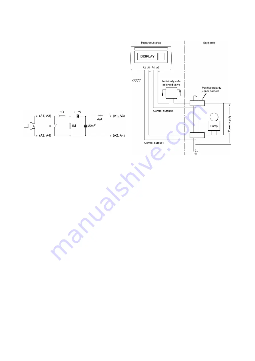
Each of the two factory fitted optional control outputs
is a galvanically isolated single pole solid state
switch as shown in Fig 3. The outputs are polarised
and current will only flow in one direction. Terminals
A1 and A3 should be connected to the positive side
of the supply.
Ron <
5
+ 0.7V
Roff >
1M
Note:
Because of the series protection diode some
test meters may not detect a closed alarm output
Fig 3 Equivalent circuit of each control output
Each control output is a separate galvanically
isolated intrinsically safe circuit with output safety
parameters complying with the requirements for
simple apparatus
. This allows the control output
terminals A1 & A2 and A3 & A4 to be connected to
almost any intrinsically safe circuit protected by a
Zener barrier having output parameters equal to or
less than:
Uo
≤
28V
Io
≤
200mA
Po
≤
0.84W
The maximum equivalent capacitance and
inductance between each set of control output
terminals is:
Ci
=
22nF
Li
=
8µH
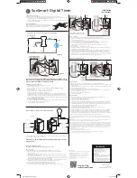
To determine the maximum permissible cable
parameters Ci and Li of the BA377E-SS should be
subtracted from the maximum permitted external
capacitance Co and inductance Lo specified by the
certificate for the Zener barrier powering the circuit
as shown in Fig 4. The internal capacitance and
inductance of other devices in the loop, such as the
solenoid valve in Fig 4, should also be subtracted
from Co & Lo.
Fig 4 Typical control output application
Summary of Contents for BA377E-SS
Page 1: ...Issue 6 4th May 2021 BA377E SS Rugged one input intrinsically safe Timer or Clock Issue 6...
Page 30: ...30...
Page 31: ...31...
Page 42: ...42...
Page 54: ...54...
Page 55: ...55...
Page 56: ...56...
Page 57: ...57...
Page 58: ...58...
Page 59: ...59...
Page 60: ...60...
Page 61: ...61...
Page 62: ...62...
Page 63: ...63...
Page 64: ...64...
Page 65: ...65...


