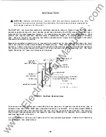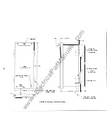
Conversion of a
PRIDE®Uni
t from surface
to
semi flush mounting or vice-versa
can
be accomplished by the
following prooedur�
1 . Conversion must be done with all external connections to the terminal block removed.
2. Disconooct connector
Jl
shown in Figure
7
from the Power Input assembly.
3 .
Remove the input cable from the cable clamp located on the left side wall of the lower
compartment.. 'Ibis clamp is not used when the
Dc
Supply is installed.
4.
Remove all wires from the terminal block.
5 .
carefully p.lll the wires through the plastic hole plug
and
remove the cable harness, with the Jl
connector, from
the
unit.
6 .
switch the two plastic hole plugs s o that the solid plug covers the hole that i s not to be used
for the external cable. The hole plug used for the cable feed-through should be mounted as
follows.
5emiflush:
Mount the feed-through plug in the hole at the rear of the unit.
Surface:
Mount the feed-through plug in the hole on the bottom left side of the unit.
7.
carefully push the wiring harness
(WI
end) through the feed-through hole plug from the inside of
the PRIDE
enclosure. (Jl connector will then be inside the lower compartmentJ
8 .
Re-attach the harness to the cable clamp on the inside of the lower compartment (Ac Supply
PRIDE
only)
•
9 . Reconnect the harness terminals to the terminal block, being careful to maintain the sequence of
wires from 1 to 12.
10 . FOr semiflush mounting, the cable
and
terminal board should be hanging from the rear of the
PRIDE.
Mount the terminal board to the four holes on the rear using the four screws and nuts supplied
wi
th
the unit.
Pull all excess cable inside the enclosure
and
secure wi
th
the cable clamp.
11. For surface mounting, mount the terminal block at any convenient location on the mounting surface.
12. Reconnect Jl to the POwer Input assembly.
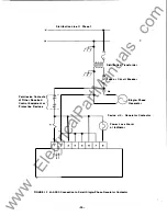
The external connections for the M-D290 Single-Phase
HUDE
are shown in Figure
II.
Figure
12
shows a
typical connection for the potential inputs of the M-0290.
The PRIDE
Relay uses a commercially available SIDT relay for the Trip
and
Close functions.
The
relay
output contact i s a type
"C"
arrangement.
One side of the
ncn
contact is wired to the external
terminal block. The relay conf iguration relative to the octal socket is shown in Figure 13. The
normally open contact or
the
normally closed contact
can
be wired to the external terminal block.
One
large blue wire is connected to either terminal
3
or
6
on the bottom of the relay socket.
A
normally
closed output contact is achieved by connecting the wire to terminal
3. A
normally open output contact
is achieved
by
connecting the wire to terminal
6.
This change
can
be easily accomplished in the field
by
switching the wire on terminals
3
or
6.
-
21
-
www
. ElectricalPartManuals
. com

