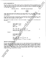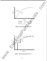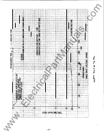
Using the vertical scale of Fig ure
3
<labeled "% FF"), the measurement time delay for any frequency
step change can be deter mined. Negative frequency step changes are treated the same as positive
changes.
FF
=
Initial
-
100%
Initial Fr equency - Final Frequency
(4 )
A
step change from 60 Hz to
55
Hz with an Under F requency setting of
58
Hz would be detected in the
next cycle after the change.
The
digital filter is implanented as follCMS:
F(n-l)t
+
FS(nt)
Wher�: F (nt)
F(nt)
=
Filter output at time nt
F(n-l)t
=
Filter output at time (n-l)t
FS(nt)
=
Latest frequency sanpl.e at time nt
2
II
NOTE:
On newer unit s wit h /::,F Transient Protection, one extra cycle will be
added to the above delays.
II
NOTE: T h e r e a r e a n umb e r o f words u s e d b y t h e p o we r indu s t ry a n d b y t h e
com p u t e r ind u s t ry t h a t appear t o b e s i m i l a r b u t , i n f a c t , have v e r y
different meanings. T h e following section refers to the definitions used by
the c o m pute r industry.
( 5)
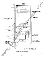
Refer to the System Flow Chart shown in Fig ure
4.
The PRIDE(!'Jsoftware runs under a " mini
n
real-time
operating system. The operating system is divided into three main parts: The Interrupt Handlers, the
Process COntroller,
and
the Kernel.
INTERRUPT HANDLERS
The
Interrupt Handlers are small routines to service the incoming interr upts. Each interrupt routine
will schedule, through the operating system, its approp riate control task (i.e. the zero-crossing
interrupt will schedule the frequency measurement task).
PROCESS CONTROLLER
The Controller's main purFQse is to process data passed to it from the interrupt handlers or from other
tasks.
The
controller can
be
broken down into four tasks.
1 .
Relay control
2.
Input conditioning
and
processing
3.
Timers and counters
4 .
Self-Tests
These tasks each have a priority assigned to them by the operating systan according to their importance
to
overall system flow.
-8-
www
. ElectricalPartManuals
. com


