background image

SELF-TEST  INDICATORS 

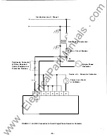
The  LEns  on  the  f ront  panel  are  used  to  indicate  Self-Test  failures  by  flashing  at  approximately 2 

cycles  per  second  when  an  error  is  detected  {refer 

to 

Figure  171. 

'!be  self-Test  errors  are  described 

in  the  following  secti� 

ROM  Failure 

Indicates  that  the  external 

RCM 

(Read  Only  Memory)  on  the  M-0298  Memory  Board 

has 

failed.  This 

can 

be 

caused  by  improper  programming  of  the ROM  or  a  partially  erased  or  defective  ROM. 

CXlRRECl'IIIE  PROCEWRE: 

Assure  that  the  M-0298  Memory  Board  is  properly  plugged  into  the  unit. 

If  the 

light  continues  to  flash,  replace  the  M-Q298  board. 

If 

this  does  not  correct 

tbe 

problem,  return  the 

PRIDE®Unit  to  the  factory. 

RAM 

.Failure 

Indicates  that  the  internal  microprocessor 

RAM 

(Random  Access  Memory) ,  external 

RAM 

or  the  M-0397 

RAM 

(if  using  the  Field  Adjustment 

Unit) 

has  failed. 

CXlRREcrIVE  PROCEWRE: 

Assure  that  the  M-0298 

(and 

M-0397  if  using  the  Field  Adj ustment  Unit)  boards 

are  properly  plugged  into 

tbe 

unit. 

If 

the  light  continues  to  flash,  replace 

tbe 

board  or  return 

tbe 

PRIDE 

Unit  to  the  factory  for  repair. 

Operating 

System 

Failure 

This  failure  mode  indicates  that  the  normal  processing  flow  has  been  upset. 

CXlRREcrIVE  PROCEWRE: 

Assure  that  the  M-Q298  (and  the  M-0397  if  using  the  Field  Adjustment  Unit)  boards 

are  properly  plugged  into  the  unit.  If  the light continues  to  flash,  replace  the  board  or  return  the 

uni t  to 

tbe 

factory. 

Power  LOSS/Frequency  Sample  Failure 

Signaled  by  a  loss  of  zero  crOSSings  on  the  frequency  measuring  inp.1t  to  the  microprocessor.  caused  by 
extremely  low  voltage  on  the  potential  input,  an  unconnected  potential  input  or  a  grossly  out  of 

specification  frequency  measuremen� 

CXlRREcrIVE  PROCEWRE: 

Assure  that  all  potential  inputs  are  properly  connected. 

Oleck  to  see  if  the 

potential  input  fuse  has  blown.  If  the  light  continues  to  flash,  return 

tbe 

unit  to  the  factory. 

� CAUTIOH: 

Prior  to  applying  power  to  the 

unit, 

double-check  a

l

connections 

to  e n s u r e   t h a t   no  w i r e s   a r e   p i n c h e d   o r   b r o k e n   and  t h a t   a l l   the  b o a r d s   a r e  

plugged  i n   completely. 

EQUIPMENT  REQUIRED 

1 .   A  Single-phase  power  source  with  frequency  range  variable  from  55  Hz  to  65  Hz 

and 

an  accuracy  of 

±..O05 

Hz 

or  better;  variable  voltage  from  60 

V  rIDS  to 

150 

V  rIDS 

with  amplitude  stability  of  :to.25% 

or  better. 

2 .   A  Digital  multimeter  Hewlett-Packard  3466A  or  equivalent. 

3 .   A  stopwatch  or  any  accurate  timing  device. 

4 .   A  fixed  120 

V, 

60 H z   (or  1 2 5 ,   48 o r  24 

d e  i f  the 

Dc 

Supply  is installed) ,  25 

power  source  for 

tbe 

power  supply  input. 

-

34

-

www 

. ElectricalPartManuals 

. com

Summary of Contents for M-0290

Page 1: ...PRIDE Voltage a Frequency Relay Single Phase M 0290 INSTRUCTION BOOK w w w E l e c t r i c a l P a r t M a n u a l s c o m ...

Page 2: ...e of the DSG would adversely affect the utility or other customers on the distribution circuit o As a permissive relay to permit reconnection of DSG when the distribution transmission line voltage has been normal for a period longer than the longest automatic reclosing cycle in use by the utility o As a general purpose relay for any combination of the following functions Overvoltage undervoltage o...

Page 3: ...d above The desired limits for these functions must be specified on the purchase order The set Xlints for all but the Undervo1tage or OVervoltage function may be changed at any time by addition of an optional M 0297 M 0397 Field Adjustment Unit which is easily installed by the user The Undervo1tage or OVervoltage set Xlints may be changed through a minor hardware modifica tion The Field Adjustment...

Page 4: ...ry The user must also choose the type of contact desired i e Normally Open or Normally Closed in the Trip state The oontact type can te changed by the user if required Contact Rating 6 A at 250 Vac 80 P F make and break 10 A at 120 Vac 80 P F make and break 5 A at 125 Vdc make and carry only Output contacts are not rated for interruption of dc circuits unless external arc suppression is used Consu...

Page 5: ...sts IlOUIITING The M 0290 is designed for either surface mounting or for serniflush mounting Units specified for surface mounting will be provided with a short cable and terminal block extending below the unit units specified for semiflush mOlUlting will be provided with the terminal block mounted to the rear surface The mounting is also field changeable EBVIRONIIEliI rAL Temperature 400 C to 800 ...

Page 6: ...h those ordered The serial number on the CERTIFICATION page an l on the unit should agree POWER INPUT AC SUPPLY CAPACITOR POWER HOLD UP OPTION Ac Supply uni ts Only DC SUPPLY Nomi nal Dc Vol tage V de 125 V dc 48 V de or 24 V de M 0319 DROPPING REGULATOR Required for operation from 250 V de Specify 125 V de for Nominal Dc Voltage OUTPUT RELAYS OUTPUT CONTACT YES NO OPEN CLOSED _ NOTE Output Relay ...

Page 7: ...TPO INT of 120 V Must be supplied by user OVERVOLTAG E SETPOINT of 120 V Must be suppl ied by user UNDER FREQUENCY HZ OVER FREQUENCY HZ UND ERVOLTAG E TRIP TIMER CYC OVERVOLTAG E TRIP T IMER CY C UND ER FREQUEN CY TRIP TIMER __________CY C OVER FREQUEN CY TRIP TIMER _________CY C RECONNECT TIMER _________SEC RELAY CON FIGURATION YES STANDARD ALTERNATE PULSE NO 59 HZ 61 HZ 3 0 CY C 10 CY C 3 0 CY C...

Page 8: ...ith Electric Co Inc are for the sale purpose of identification IDE IIWillIiS l IIIlIOO S H IFICATI JIS EB IalFD HEREIN ARE IDE PIlOPIUETARY PkJPERl IX IIElCKIfrJB EUX mIC ro INC lIND ARE ISSDID IN STRICT X NFIIEQI SHALL lUI BE USED lIS A BASIS IX REPR JXJCTICII IX IDE APPlIRAroS IESCRIBED DIEREIN WI lJDJT liRIT lUI PEalISSICli IX BtX KWl JB EUX mIC D nco NO ILLUSTRAT ION O R DESCRIPTION CONTAINED ...

Page 9: ...ways disconnect power and discharge circuits before working on the unit EXERCISE CARE DURING INSTALLATION OPERATION AND MAINTENANCE PROCEDURES The equipment described in this manual contains voltages high enough to cause serious lnJury or dea Dnly qualified personnel should install operate test and maintain this eq uipment Be sure that all personnel safety procedures are carefully followed Exercis...

Page 10: ...uency Measurement Time Curve Figure 3 7 System Software Description 8 System Flow Chart Figure 4 9 Electrical Description 11 Ac Supply 11 Dc Supply 11 Block Diagram Figure 5 12 Power Loss Time Delay Figure 6 13 Capacitor Power Hold Up Option 14 Mechanical 16 Mechanical Configuration Figure 7 17 Installation 18 Semiflush Mounting Screw Figure 8 18 Mounting Outline Dimensions Figure 9 19 Hole Drill ...

Page 11: ...gure 15 2 9 Changing the Frequency Setpoints and Timers 30 Maintenance 31 M 0315 PRIDE Test Adapter 31 Troub1 eshooti ng 31 Replacement Fuses Table 3 32 Location of Input Fuse s Output Relays Figure 16 33 FUnctional Test Procedure 34 Self Test Error Indicators Figure 17 35 M 0297 M 0397 Field Adjustment Unit Installed in the M 0290 38 Design Changes 39 warranty and Indemnification 41 In our effort...

Page 12: ...re complex programming of other protective relay functions The PRIDE Unit therefore is aWlicable as a general purpJse multifunction protective relay BACKGROUND A survey was conducted of the two hundred largest utilities and of the IEEE Disper sed Storage and Generation Working Group concerning utility relaying policies relating to interconnection of parallel generation Upon completion of this surv...

Page 13: ...re a multi function voltsge and frequency relay is needed The relaying provided is listed in Table 1 Refer to the SPECIFICATIONS for a complete description of the adjustment ranges and of the accuracy of each of the relaying flDlctions DEVICE M 0290 FUNCTION NUMBER S INGLE PHASE Undervoltage 27 X Overvoltage 59 X Under Frequency 81U X Over Frequency 810 X Undervoltage Trip Timer 2UV X Overvoltage ...

Page 14: ...oss Detection are incortx rated in the software of the PRIDE Units 1 Any frequency measurement above 80 Hz and below 40 Hz will be ignored This is the Frequency Blocked State and will be indicated by both frequency LEOs turning on 2 If n o zero crossings a r e detected for approximately 0 5 sec or if the voltage falls below 0 45 p o the frequency measurement will also be blocked therefore frequenc...

Page 15: ...ELAY CONFIGURATION I N r l I I LL j PICKUP TIME DELAY LOGICAL 0 TO 1 6 f3v tr I DC _ J I IcAPAcrrool DROPOUT TIME DEL LOGICAL 1 TO 0 I I IWIOWAIE I POWER l 1 I SUPPLY r J I HOLD UP I 0 o NJ LQP 9JLJ I OVER h I v V MAX I VOLTAGE I H F2 NSN N UT 6 N F FMAX V F FMN FIGURE 1 Functional Diagram I 1 1 I f I cri 1 3 l 1 I 0 I 3 I I I Il rr v I T NO I Kl b I NC I w w w E l e c t r i c a l P a r t M a n u ...

Page 16: ... the Alternate Relay COnfiguration except the output relay will only energize for 0 5 sec when the Trip condition is met This option will be used in circuit breaker awlications where the trip signal will be momentary III NOTE It is important t o r emember that the three Output Relay Configuration options a r e separate f r o m the the Output Contact option which is chosen as n o r m a lly open o r...

Page 17: ...shown to clarify this technique Refer to Figure 2 for definitions of the terms Example 1 Exanple 2 Initial Voltage 120 V Final Voltage 140 V Setpcint 130 V vstep 20 V Vset 10 V Vset 130 120 10 X 100 X 100 50 vstep 140 120 20 Time Delay fran Figure 2 0 16 sec 9 6 cycles Initial Voltage 120 V Final Voltage 100 V Setpcint 108 V Vset 120 108 12 X 100 X 100 60 Vstep 120 100 20 Time Delay fran Figure 2 ...

Page 18: ...TRIPPED TRIPPED 0 SEC V TA F T VOLTAOESETllNG T V_ V 1 NTIAL VOlTAGE L FIGURE 2 Voltage Mee urement Time Curve NOT TRIPPED I TRIPPED TNE CYCLES FIGURE 3 Frequency Me urement Time Curve 7 7 7 w w w E l e c t r i c a l P a r t M a n u a l s c o m ...

Page 19: ... a c t have very different meanings The following section refers to the definitions used by the computer industry 5 Refer to the System Flow Chart shown in Figure 4 The PRIDE Jsoftware runs under a minin real time operating system The operating system is divided into three main parts The Interrupt Handlers the Process COntroller and the Kernel INTERRUPT HANDLERS The Interrupt Handlers are small ro...

Page 20: ...EMENr TRIP TIMER TIMER SETPOINT YES OPEN RELAY YES NO SELF TESTS ERRORS NO MEASURE FREQUENCY MEASURE VOLTAGE OK YES FIGURE Syatem Flow Chart 11 YES INCREMENT RECQIII CT Tt IER CLOSE RELAY NO w w w E l e c t r i c a l P a r t M a n u a l s c o m ...

Page 21: ...will be described in more detail in the MAINTENANCE sectio KERNEL The nucleus of the operating system is the Kernel The Kernel is comp sed of two parts 1 The Scheduler 2 The Dispatcher Scheduler he Scheduler is flagged from an interrupt driver that is waiting for a task to be performed Status bits are set by the scheduler to indicate that a task is pending and then control is returned to the runni...

Page 22: ...ry for operation of the digital and analog circuits A Power Loss Detector is incorporated to warn if the the power supply fails The Power Loss Detector feature is described in detail below Power Loss Detector When the power suWly fails the input power is lost or if the input power fuse blows the Power Loss Detector will 1 Reset the microprocessor 2 De energize the Kl output relay this will be the ...

Page 23: ... POWER i 4 I POWER 1 SUPPlY I j J WATCH DOG TIMER l GND 5V L _ l J RESET J POWER ON CLEAR ADDRESS DATAf CONTROL 1 __ 1 SQUARING f CIRCUIT OVER VOLTAGE DETECTOR UNDER VOLTAGE f DETECTOR AC TO DC AC IN I O PORTS FIGURE 15 Block Diagram 12 I LED DRIVE RELAY DRIVE I w w w E l e c t r i c a l P a r t M a n u a l s c o m ...

Page 24: ...F H f h H r r rT I I T j I p J r j T t i r j t j j r H r t I __ L T _ l _ I 1 c t i _ 13 iI t r T ct H I t j H Q E i o J o G CI 1 1 It I C I ii w w w E l e c t r i c a l P a r t M a n u a l s c o m ...

Page 25: ...og will reset the microprocessor back to an orderly start up sequence if the program flow is upset or if the software does not perform an operation within the allotted time period The microprocessor will periodically update or refresh the watchdog to keep it out of a reset conditi POWER ON CLEAR The Power On Clear block is an RC circuit which insures that a proper Power Up sequence has been accomp...

Page 26: ...and time delay synchronizatio The ROM Read Only Memory Memory Board M Q298 contains the program for the microprocessor The ROM also stores the setpoints programmed at the time of manufacture The Field Adjustment Unit M 0297 M 0397 can be added to allow programming all but the OVer and Undervoltage setpoints Refer to the FIElD AIlJUSTMERT section for further details CAUTION The ROM i s of the u l t...

Page 27: ...e entering the Power Supply and Processor Logic section The EM filters serve a dual pur X se The external interference on the power and X tential inputs is prevented from entering the sensitive circuit area Also the inherent noise generated by the microprocessor and switching regulator is prevented from leaving the relay and interfering with other equipnent CAUTIOH Do not apply any f o r m of test...

Page 28: ...I I M 0397 EE PROM BOARD OPTION J4 M 0298 MEMORY BOARD _ _____ MOTHER BOARD rL I J3 l J l POWER SUPPLY FILTERS DC SUPPLY _ _ _ J OR CAPACITOR POWER HOLD UP OPTION XFMRS RELAY I I I I REAR T 8 FOR SEMIFLUSH MOUNTING CABLE AND T B FOR I I SURFACE MOUNTING FIGURE 7 Mechenlcal Configuration 1 7 w w w E l e c t r i c a l P a r t M a n u a l s c o m ...

Page 29: ... be 10 32 screws four are required Refer to Figure 8 for choosing the length of the mounting screws for semiflush mounting The length of the screw should not exceed 1I4n from the back side of the mounting lip The total length should be 1 4 plus the thickness of the panel 0 32 PEM N U T PART O F FLANGE GASKET NOT SHOWN COVER MOUNTING FLANGE L MOUNTING PANEL OF THICKNESS T 1 0 32 SCREW r USER SUPPLI...

Page 30: ... I t rJ 17 7116 f 1 2 MAX l r cLr 11 1 8 v REAR T B 1 FOR SEMI FLUSH _ 1 _ lit MOUNTING I I 1_ _ It 16 SURFACE MOUNT ONLY 4 PLACES GROUND LUG FOR SURF ACE M O U NT ONLY U 1I I I 6 5 16 t 5 8 r I 1 I CABLE T B FOR SURFACE MOUNTING FIGURE 9 Mounting Outline Dimensions w w w E l e c t r i c a l P a r t M a n u a l s c o m ...

Page 31: ...USH I 1 I MOUNT ONLY I 4 P LACES I I l FOR SURFAC MOUNT ONLY 4 PLAC ES I I I I I I I Ii tn 5 311 II 3 4 7 5 1 11 7 1 12 FIGURE 10 Hole Drill Cutout Dimensions 20 I 1 8 1 8 1 7 1 14 1 0 0 6 II I H I 2 1 12 w w w E l e c t r i c a l P a r t M a n u a l s c o m ...

Page 32: ...erminal block being careful to maintain the sequence of wires from 1 to 12 10 FOr semiflush mounting the cable and terminal board should be hanging from the rear of the PRIDE Mount the terminal board to the four holes on the rear using the four screws and nuts supplied with the unit Pull all excess cable inside the enclosure and secure with the cable clamp 11 For surface mounting mount the termina...

Page 33: ... 1 1 T 2 3 4 5 6 7 K4 L 8 9 1 0 1 1 1 2 AC D H N N H O UTPUT CONTACT POWER INPUT SENSING INPUT POWER LOSS NOT USED FIGURE 1 1 Exlernal Connections 22 w w w E l e c t r i c a l P a r t M a n u a l s c o m ...

Page 34: ...nt or Protective Device F l DI trlbutlon Tr nolormer Fuoe or Circuit Breaker Blngle Pha e Generator Oevlce 4 Generator Cont ctor Power Lo Alarm or Indicator FIGURE 1 2 M 0290 Connection to Small Single Phase Generator Contactor 23 w w w E l e c t r i c a l P a r t M a n u a l s c o m ...

Page 35: ...e PRIDE Unit may be added by changing from an SPOT to a DPDT octal socket relay i e Potter Brumfield KRPllADG 12VDC Beckwith Electric Part 43160 The contact ratings for the additional contact are the same as those given for the normal output contacts Connections to the relay socket for the normal output contact must be changed from relay socket terminal 3 to terminal 4 for the normally closed cont...

Page 36: ...g if the frequency is within the M 0290 setpoints The digital filter will produce a transient OUtpllt for several cycles after a phase shift takes place However the Power Loss software will throw away a period that changes more than 273 AlS from the previollsly measured period This corresponds to an apparent phase shift of 60 A phase shift of less than 60 will cause a temporary response from the d...

Page 37: ...TINGS CYCLES 9 8 7 6 5 4 3 2 1 O F 60 60 1 UF 60 5 9 9 5 9 8 60 5 59 5 60 9 6 1 59 2 59 1 59 SETPOINT Hz FIGURE 14 Minimum Under Over Frequency Trip Timer Settings 28 62 58 w w w E l e c t r i c a l P a r t M a n u a l s c o m ...

Page 38: ...Under Frequency VOLTAGE IIEASURBIIEBT 1 Oller and UndeIVoltage OUTPUT RELAY CONFIGURATION 1 Standard Relay Configuration 2 Alternate Relay Configuration 3 Pulse Relay Configuration 27 w w w E l e c t r i c a l P a r t M a n u a l s c o m ...

Page 39: ... section and J4 from the Mother Board 6 On PRIDEs with printed circuit board retainers on each corner o f the Mother Board use a small needle nose pliers or flat screwdriver to s ueeze the retaioor tabs together ling the board out at each corner as you do so On newer PRIDEs remove the four retaining screws at each correr 7 Remove the Mother Board by tilting it forward and around the four screw mOL...

Page 40: ... 17 8 n 2 4 698 n 4 5 976 n 5 6 1 24 K 6 10 2 37 K l0 15 3 83 K 15 20 5 49 K 20 TABLE 2 Voltage Setpolnta Realator Values o o o R 2 1 R 1 0 O l e rvoltaga Select Resistor Undervoltage Select Resistor P4 o TP1 FIGURE 15 Mother Board 29 P 0583 o o o TP5 TP6 o 0 J w w w E l e c t r i c a l P a r t M a n u a l s c o m ...

Page 41: ...to the DES IGN CHANGES s e c t i o n o f this m a n u a l f o r an explanation of the differences When ordering a new Memory Board from Beckwith Electric specify the new settings required When the new board is received remove the old board by carefully sliding it out of its slot see Figure If you are exchanging Memory Boards place the old Memory Board in the antistatic bag and shipping carton and ...

Page 42: ...kmanship or failure of material If a unit is under warranty aOO express shitxnent for return of the repaired unit is requested shipping charges will be billed at the current rate If the fault is due to abuse or misuse or is out of warranty a modest charge will be made Repair can normally be expected to take two weeks plus shipping time If faster service is required it should be requested at the ti...

Page 43: ...d a nominal r e pa i r charge w i l l be made f o r r eplacement o f the f use Please c h e c k the f u s e s before r e t u r n i n g the PRIDE f o r r epai r i n order to avoid unnecessary repair charges canponent Beckwith Electric Number Description Fl 42719 Plug in Microfuse 1 A Littelfuse 273 001 F2 42725 Plug in Microfuse 112 A Littelfuse 273 500 CAUTION Be careful to replace the fuses only ...

Page 44: ...I II l i i P T 1 OWER LOSS TRIP AND CLOSE ffi I l I I K 1 I I I L _ _ _ J M 0290 SPARE FUSES ARE TAPED TO THE INSIDE OF THE ENCLOSURE IN THIS COMPARTMENT FIGURE 18 Locallon of Input Fuses Output Relays 33 w w w E l e c t r i c a l P a r t M a n u a l s c o m ...

Page 45: ...sure that the M Q298 and the M 0397 if using the Field Adjustment Unit boards are properly plugged into the unit If the light continues to flash replace the board or return the unit to tbe factory Power LOSS Frequency Sample Failure Signaled by a loss of zero crOSSings on the frequency measuring inp 1t to the microprocessor caused by extremely low voltage on the potential input an unconnected pote...

Page 46: ...E 0 0 0 POWER OK FLASHING LAMPS INDICATE OVER UNDER FREQUENCY i RAM FAILURE ROM FAILURE OPERATING SYSTEM FAILURE FIGURE 17 Selt Tesl Error Indlcalors 315 INPUT LOSS FREQUENCY SAMPLE FAILURE w w w E l e c t r i c a l P a r t M a n u a l s c o m ...

Page 47: ...flash the LDlit is defective IIINOTE If the M 0297 M 0397 Field Adjustment Unit i s present various setpoints and t i m e r delay values especially the Reconnect T i mer c a n be changed to speed up t e s ting In addition f r equency values and t i m e r progress can be monitored as pa r t of a test procedure Refer to the M 0297 M 0 3 9 7 Instruction Book f o r f u r ther details UNDERIOVER FREQUE...

Page 48: ...e input voltage from 120 V to about 10 higher than the OVervoltage setpoint 2 The measured time delay should be 112 cycle or l of the calculated Total Time Delay whichever is greater Undervoltage Trip Timer 1 Return the input to 120 V and wait for the Kl relay to change state 2 Lower the input to about 10 below the Undervoltage setpoint 3 The measured trip time delay should be 1 2 cycle or l of th...

Page 49: ...us trip status has been erased M 0297 PRIDE CONTROL UNIT 1 Be sure that the cable on the M 0297 PRIDE Control Unit is properly installed in the socket on the M 0397 board If the Control unit is not plugged in turn the power switch to OFF before cormecting the lDlit 2 Refer to Table 3 ITalid Show Status Function Numbers in the M 0297 M 0397 Instruction Book and cbeck each function 3 Refer to Table ...

Page 50: ...0290 relays must be updated Return the PRIDE to Beckwith Electric for modifi cation if you wish to use the Field Adjustment Uni II M 0290 SERIAL NUMBERS 0010 TO 0048 EXCLUDIRG 0034 0042 0 0 43 ABO 0044 Relays in this group were originally supplied with software versicn DOOOlVOl xx Ibis software carmot be used with the Field Adjustment Unit This version does JlQt incoqX lrate all the features descr...

Page 51: ...ht when the parameters go out of the setp lint range oOOOlV03 01 and higher DOOOlV04 XX This is the current software version It incoqncates all the above mentioned features plus 1 lidded ability to program the Output Relay configuration 2 Changed the operation of the Trip Targets see M 0297 M 0397 Instruction Book 3 Improved input noise inmunity F Transient Protectioo III NOTE A software update fo...

Page 52: ...voiced to the Seller at the time of return INDEMNIFICATION The Seller shall not be liable for any property damages whatsoever or claims of any kind whether based on contract warranty tort including negligence or otherwise or for any loss or damage arising out of connected with or resulting from this contract or from the performance or breach thereof or from all services covered by or furnished und...

Page 53: ...w w w E l e c t r i c a l P a r t M a n u a l s c o m ...

Reviews: