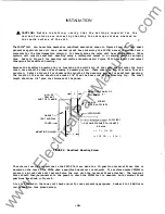
Therefore, the farther the setpoint is from
60
Hz,
the
greater the hysteresis.
'!he
time delays for tripping
am
reclosing use an internal crystal oscillator
as
a clock.
'lhe time
delays in Figure
1
provide a delay only on an input transition from a logic low to a logic hig�
No delay is incorporated from a logic high to a logic low.
The
voltage
and
frequency time delays are
used to delay triwing, ensuring that a transient condition will not cause an unnecessary trip.
The
Reconnect Timer
can
be programmed for
up
to
1092
seconds to ensure the system is stable
and
reclosers
have
all
completed their sequences before reconnection.
As stated in the SPECIFICATIONS and shown in Figure
1,
one of the following three output relay
configurations is possibl�
The Standard Relay COnfiguration (Position
1)
will be used in most OOG awlications where
any
power
loss or Self-Test error will cause the relay to de-energize. This is defined as the Tripped state in
this configuration.
The Alternate Relay COnfiguration (Position
2)
will be used in larger power plant awlications, where
a Self-Test error or power loss to the uni t will not cause the PRIDE®to trip the generator off-line.
When in the Alternate Relay COnfiguration, the output relay will energize when the Trip condition is
met (i.e., when a Trip Timer times out, the Trip output relay will energize) .
Self-Test errors or
power loss will de-energize the output relay, defined as the Close state.
The PUlse Relay COnfiguration (Position
3)
is logically the same
as
the Alternate Relay COnfiguration,
except the output relay will only energize for
0.5
sec when the Trip condition is met.
This option
will be used in circuit breaker awlications where the trip signal will
be
momentary.
III
NOTE: It is important
t o r emember that the three Output Relay Configuration
options a r e separate f r o m the the Output Contact option which is c h o sen as
n o r m a lly open o r n o r m ally closed.
The total time delay for the PRIDE Unit to trip or close is composed of two independent componenta.
1.
The time delays specified in the OVer/Undervoltage Trip Timers, Over/Under Frequency Trip
Timers and Reconnect Timer.
2 .
'lbe measurement time delay for the internal circuitry to detect the change in the input condition.
The measurement time must
be
added to the time delay specified for the OVer/Undervoltage Trip Timers,
Over/Under Frequency Trip Timers
and
Reconnect Timer.
The measurement time
can
be
determined using the LED indicators on the front paneL
The measurement
time is defined
as
the time between the change in the input condition (i.e., the voltage or frequency
shift) and the front panel
LED
turning "ON" (or alternately turning "OFF" for an input condition
shifting into range) .
The
intentional time delay programmed in the Trip Timers or the Reconnect Timer
can
be determined by
measuring the time delay between when the LED changes state and when the relay contacts change state.
This time includes a minimum time of
1
cycle for tPe outplt relay to operate.
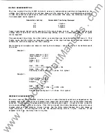
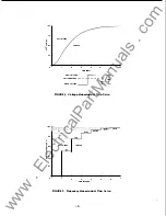
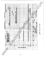
A technique to determine a close estimation of what the measurement time delay will be for various
input conditions is described in the following sections.
-
5
-
www
. ElectricalPartManuals
. com


