background image

Installation Guide

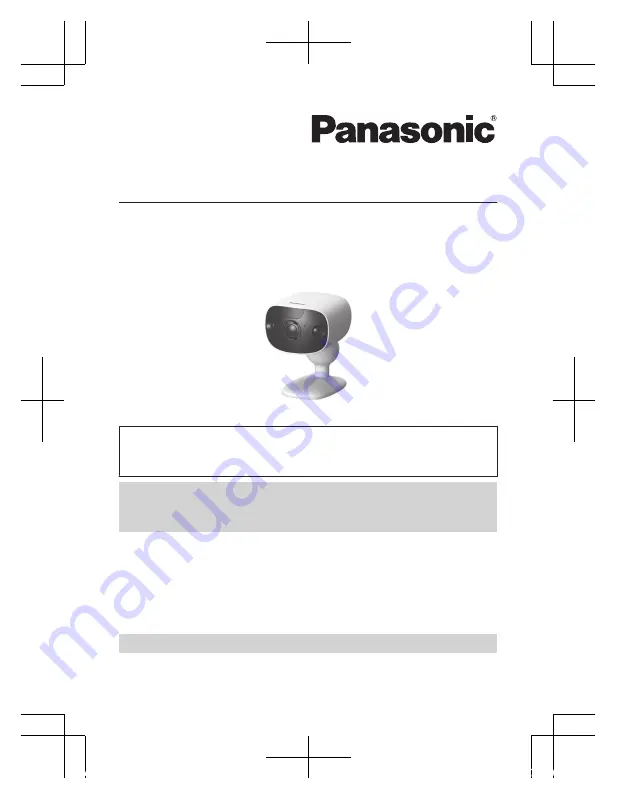
Home Monitoring Camera

HomeHawk Outdoor

Model No.    

KX-HNC710

Thank you for purchasing a Panasonic product.

This document explains how to install the outdoor camera properly.
Refer to the Installation Guide supplied with KX-HN7001/KX-HN7002/
KX-HN7003 for details.

Charge the camera for about 7 hours before camera installation
(page 14). Then register the camera to the access point
(page 16).

Please read this document before using the unit and save it for future
reference.

For assistance, please contact us at 1-800-272-7033 or visit our Web
site: 

http://shop.panasonic.com/support

 for customers in the U.S.A.

Please register your product: http://shop.panasonic.com/support

Printed in China

HNC710_(en_en)_0207_ver.110.pdf   1

2018/02/07   20:11:46

Summary of Contents for HomeHawk KX-HNC710

Page 1: ...ails Charge the camera for about 7 hours before camera installation page 14 Then register the camera to the access point page 16 Please read this document before using the unit and save it for future reference For assistance please contact us at 1 800 272 7033 or visit our Web site http shop panasonic com support for customers in the U S A Please register your product http shop panasonic com suppo...

Page 2: ... location examples 10 Do not install in these locations 11 Setup Part names and functions 13 Charging the camera 14 Charging LED indicators 15 Turning the power on for the camera 16 Registering the camera 16 Confirming the camera installation area 17 Installation 17 Accessing the User s Guide 20 Appendix Specifications 21 FCC and other information 21 Customer services 23 Limited Warranty ONLY FOR ...

Page 3: ...on wire tool A B C D Other information R Design and specifications are subject to change without notice R The illustrations in these instructions may vary slightly from the actual product R HomeHawk Outdoor is referred to as outdoor camera or camera in this document Trademarks R Android and Google Play are registered trademarks or trademarks of Google Inc R Microsoft Windows and Internet Explorer ...

Page 4: ...em it is not designed to provide complete protection from property loss Panasonic will not be held responsible in the event that property loss occurs while this system is in operation R The system s wireless features are subject to interference therefore functionality in all situations cannot be guaranteed Panasonic will not be held responsible for injury or damage to property that occurs in the e...

Page 5: ...ccident R Do not allow the power cord to be excessively pulled bent or placed under heavy objects R Do not mount the bracket in a location higher than 2 2 m 7 feet 3 inches in an unstable location in a location subject to frequent vibration on a ceiling or on a weak wall Do not mount on gypsum board concrete blocks wooden materials exposed to the outdoors walls with very rough surfaces or surfaces...

Page 6: ...is camera conforms to the IP6X code do not intentionally expose it to grit and dust IP6X indicates that the product is protected against grit and dust this product has shown the capabilities of preventing dust from entering inside the product after the product was in a device that contained dust with a diameter of 75 µm or less for 7 hours and was shaken and removed from that device R The USB cabl...

Page 7: ...r information This product has a rechargeable lithium ion battery Do not throw into fire apply heat or charge use or leave in a high temperature environment Doing so may cause fluid leak overheating or explosion Routine care R Wipe the outer surface of the product with a soft moist cloth R Do not use benzine thinner or any abrasive powder Camera image quality R Camera images may have the following...

Page 8: ...ctions in the operating instructions Remove the built in rechargeable battery before disposing of the cameras Do not dismantle or replace the battery so that you can use the camera again This could cause fire or an electric shock Replace it at an authorized service center Battery removal procedure R Disconnect the power cord from the camera when removing the battery 1 2 3 4 6 5 8 7 2 2 Battery R P...

Page 9: ...Notice For assistance please visit http shop panasonic com support 9 Important Information HNC710_ en_en _0207_ver 110 pdf 9 2018 02 07 20 11 47 ...

Page 10: ...Approx 6 m 19 feet 8 inches Visitors pass in front of the camera from side to side cars in the street are less likely to cause false detections Cars in the street are more likely to cause false detections Note R The visual detection range is as follows Horizontal 150 Vertical 85 10 For assistance please visit http shop panasonic com support Installation Location HNC710_ en_en _0207_ver 110 pdf 10 ...

Page 11: ...zontal 150 Vertical 85 Do not install in these locations Installing in the following areas may cause deformation discoloration malfunction or operational failure R In direct sunlight or directly under an outdoor light even if the surroundings are within operational temperature range parts of the product may become hot R Areas subject to frequent vibration shock or impact R Near fire heating device...

Page 12: ...s R Areas where objects such as trees or hanging laundry move due to wind temperature variation and motion may cause false detections R Areas affected by breezes from fans air conditioning unit compressors water heaters or car exhaust severe temperature variations may cause false detections R Areas subject to severe weather such as strong wind camera shake can cause false detections or rain strong...

Page 13: ...USB connector G Interface cover N Wall mounting adaptor LED indicators You can use the LED indicators to confirm the camera s status LED indicator Status Off R No power R More than 5 seconds have passed since turning on the power when the camera is not registered to the access point R LED indicator is turned off 1 For assistance please visit http shop panasonic com support 13 Setup HNC710_ en_en _...

Page 14: ...oint 1 3 1 You can configure the camera so that its LED indicator does not light during normal operation For more information refer to the User s Guide page 20 2 The LED indicator lights in amber for 5 seconds after the power is turned on for the camera 3 The signal level strong good weak out of range is shown after pressing MSETUPN for 3 seconds Charging the camera R This camera has an internal r...

Page 15: ...or more than 10 seconds after connecting the USB cable If the indicator stops blinking and turns off within 10 seconds perform the following If you are not using the supplied USB cable use it If the indicator still turns off within 10 seconds try connecting the USB cable to a different power source 5 0 V 1 0 A or higher Charging LED indicators You can use the charging LED indicators to confirm the...

Page 16: ...cted and the access point is powered Using registration buttons 1 Access point Press and hold MSETUPN until the LED indicator 1 blinks slowly in green 1 2 Camera Press and hold MSETUPN until the LED indicator 2 blinks slowly in green 2 R When registration is completed the camera sounds one long beep Note R If registration fails the camera sounds several short beeps Using the app You can change the...

Page 17: ...acity of each screw is at least 294 N 30 kgf R If the weight of the camera is supported by the siding only the siding could become damaged Make sure you mount the camera in a location where the structure behind the siding can be used to support the weight of the camera If this is not possible due to the thickness of the siding use commercially available screws ø4 mm longer than 25 mm ø5 32 inches ...

Page 18: ... Depending on the type of ALC panel you may not be able to attach the camera Consult the ALC panel manufacturer R Do not use the included screws After consulting the manufacturer of the ALC panel use only commercially available metal screw anchors screw ø4 mm 5 32 inches designed for ALC panels R Carefully read the instructions supplied with the anchors Follow instructions regarding drill bit diam...

Page 19: ...Make sure to close the interface cover securely Water resistance cannot be assured if the interface cover is open 4 Drive the wall mounting screws into the wall 1 Longer than 25 mm 1 inch 2 Space 2 8 mm 1 8 inches 1 2 Note R Use the following template when determining the location of the screw holes 1 inch 25 4 mm 5 Mount the wall mounting adaptor to the wall Next attach the safety wire to the wal...

Page 20: ...ing adaptor Accessing the User s Guide The User s Guide is a collection of online documentation that helps you get the most out of the HomeHawk app 1 Tap in the app s home screen 2 Tap User s Guide Note R Android 4 1 or later versions are recommended R You can also access the User s Guide at the web page listed below https panasonic net cns pcc support homehawk manual R Microsoft Windows Internet ...

Page 21: ...P rating IP65 4 R Dimensions height width depth Approx 98 mm 71 mm 94 mm 3 7 8 inches 2 13 16 inches 3 11 16 inches 5 R Mass weight Approx 490 g 1 08 lb 5 1 Only when charging 2 Battery performance changes depending on the surrounding temperature frequency of use and the actual usage environment For more information refer to the User s Guide page 20 3 The infrared LEDs that surround the camera len...

Page 22: ...enna Increase the separation between the equipment and receiver Connect the equipment into an outlet on a circuit different from that to which the receiver is connected Consult the dealer or an experienced radio TV technician for help Some devices operate at frequencies that may cause interference to nearby TVs and VCRs To minimize or prevent such interference this device should not be placed near...

Page 23: ...r Panasonic products Accessories Parts for your Camera Phone A V products TV Computers Networking Personal Care Home Appliances Headphones Ba eries Backup Chargers more For Product Informa on Opera ng Assistance Parts Owner s Manuals Dealer and Service info go to http shop panasonic com support For the hearing or speech impaired TTY 1 877 833 8855 As of June 2015 For assistance please visit http s...

Page 24: ...atteries antennas and cosmetic parts cabinet This warranty only applies to products purchased and serviced in the United States This warranty is extended only to the original purchaser of a new product which was not sold as is Home Network System Products microSD card Included model only 90 days N A When shipping the unit carefully pack include all supplied accessories listed in the Owner s Manual...

Page 25: ...s attributable to acts of God THERE ARE NO EXPRESS WARRANTIES EXCEPT AS LISTED UNDER LIMITED WARRANTY COVERAGE THE WARRANTOR IS NOT LIABLE FOR INCIDENTAL OR CONSEQUENTIAL DAMAGES RESULTING FROM THE USE OF THIS PRODUCT OR ARISING OUT OF ANY BREACH OF THIS WARRANTY ALL EXPRESS AND IMPLIED WARRANTIES INCLUDING THE WARRANTY OF MERCHANTABILITY ARE LIMITED TO THE PERIOD OF THE LIMITED WARRANTY PARTS AND...

Page 26: ...26 Notes HNC710_ en_en _0207_ver 110 pdf 26 2018 02 07 20 11 47 ...

Page 27: ...27 Notes HNC710_ en_en _0207_ver 110 pdf 27 2018 02 07 20 11 48 ...

Page 28: ...the power slide switch of the camera ON OFF B For your future reference We recommend keeping a record of the following information to assist with any repair under warranty Serial No Date of purchase found inside the interface cover on the bottom of the unit Name and address of dealer Attach your purchase receipt here Two Riverfront Plaza Newark NJ 07102 5490 Panasonic Corporation 2018 HNC710_ en_e...

Page 29: ...mara durante aproximadamente 7 horas antes de instalar la cámara página 8 A continuación registre la cámara en el punto de acceso página 10 Lea este documento antes de usar la unidad y guárdelo para consultarlo en el futuro Para obtener ayuda comuníquese con nosotros llamando al 1 800 272 7033 o visite nuestro sitio web http shop panasonic com support para clientes en los EE UU solo en inglés Por ...

Page 30: ...res de los componentes y funciones 7 Cómo cargar la cámara 8 LED indicadores de carga 9 Encender la alimentación para la cámara 10 Cómo registrar la cámara 10 Confirmación del área de instalación de la cámara 11 Instalación 11 Acceso a la Guía del usuario 14 2 Tabla de Contenido HNC710_ es_es _0208_ver 110 pdf 2 2018 02 08 20 45 10 ...

Page 31: ...Aprox 6 m 19 pies 8 pulgadas Los visitantes pasan en frente de la cámara de lado a lado y es poco probable que los vehículos en la calle generen detecciones fal sas Es más probable que los vehículos en la ca lle generen detecciones falsas Nota R El rango de detección visual es el siguiente Horizontal 150 Vertical 85 Para obtener ayuda visite http shop panasonic com support 3 Ubicación de la instal...

Page 32: ...bable que los vehículos en la calle generen detecciones fal sas R Para evitar que los vehículos altos oscu rezcan los rostros ajuste la posición de instalación y el ángulo de la cámara Es más probable que los vehículos en la ca lle generen detecciones falsas Nota R El rango de detección visual es el siguiente Horizontal 150 Vertical 85 4 Para obtener ayuda visite http shop panasonic com support Ub...

Page 33: ... producto R Cerca de televisores radios equipos de oficina automáticos como ordenadores aires acondicionados paneles para calentar agua con intercomunicador o equipos de seguridad para el hogar pueden generar ruido R Cerca de receptores de transmisión satelital como sintonizadores televisores con sintonizadores satelitales incluidos y grabadoras es posible que las imágenes transmitidas se distorsi...

Page 34: ...ios que pueden interferir con la detección de la variación de temperatura R Áreas donde el brillo cambia con facilidad R Áreas donde haya luces de fondo los rostros se oscurecen y son difíciles de identificar como las siguientes Áreas donde la mayor parte del fondo es el cielo Áreas donde la luz del sol se refleje en una pared blanca o fondo Áreas brillantes como aquellas expuestas a la luz del so...

Page 35: ...micro USB G Tapa de interfaz N Adaptador de instalación en pared Led indicadores Puede usar los Led indicadores para confirmar el estado de la cámara Led indicador Estado Apagado R Sin energía R Han transcurrido más de 5 segundos desde que se encendió la alimentación cuando la cámara no está registrada en el punto de ac ceso R El indicador LED está apagado 1 Para obtener ayuda visite http shop pan...

Page 36: ... alcance del punto de acceso 1 3 1 Puede configurar la cámara de forma tal que el Led indicador no se encienda durante el funcionamiento normal Para obtener más información consulte la Guía del usuario página 14 2 El indicador LED se ilumina en ámbar durante 5 segundos después de que se encienda la alimentación para la cámara 3 El nivel de la señal fuerte bueno débil fuera del alcance se muestra d...

Page 37: ... más de 10 segundos después de conectar el cable USB a la cámara Si el indicador deja de parpadear y se apaga dentro de los siguientes 10 segundos realice lo siguiente Si no está usando el cable USB suministrado úselo Si el indicador se sigue apagando dentro de los siguientes 10 segundos intente conectar el cable USB en una fuente de alimentación eléctrica diferente 5 0 V 1 0 A o superior LED indi...

Page 38: ... esté encendido Uso de los botones de registro 1 Punto de acceso Mantenga oprimido MSETUPN Configuración hasta que el indicador LED 1 parpadee lentamente en verde 1 2 Cámara Mantenga presionado MSETUPN Configuración hasta que el indicador LED 2 parpadee lentamente en verde 2 R Cuando se ha completado el registro la cámara emitirá un pitido largo Nota R Si el registro falla la cámara emitirá varios...

Page 39: ... 30 kgf R El revestimiento podría dañarse si el peso de la cámara se sostiene solo con el revestimiento Asegúrese de montar la cámara en un sitio donde la estructura detrás del revestimiento pueda usarse para sostener el peso de la cámara Si no es posible debido al grosor del revestimiento use tornillos disponibles de forma comercial de ø4 mm más largos de 25 mm ø5 32 pulgadas más largos de 1 pulg...

Page 40: ... de panel de ALC es posible que no pueda colocar la cámara Consulte al fabricante del panel de ALC R No use los tornillos incluidos Después de consular al fabricante del panel de ALC use solo taquetes de metal disponibles de manera comercial tornillo ø4 mm 5 32 pulgadas diseñados para los paneles de ALC R Lea con atención las instrucciones suministradas con los taquetes Siga las instrucciones sobr...

Page 41: ...able de seguridad E 4 5 1 2 3 Importante R Asegúrese de cerrar la tapa de la interfaz de forma segura No se puede asegurar la resistencia al agua si la tapa de la interfaz está abierta 4 Coloque en la pared los tornillos de instalación en pared 1 Más largo que 25 mm 1 pulgada 2 Espacio de 2 8 mm 1 8 pulgadas 1 2 Nota R Use la siguiente plantilla cuando determine la ubicación de los orificios de lo...

Page 42: ...gue de la cámara o del adaptador de instalación en pared Acceso a la Guía del usuario La Guía del usuario es una colección de documentación en línea que lo ayuda a aprovechar al máximo la aplicación HomeHawk 1 Toque en la pantalla de inicio de la aplicación 2 Toque Guía del Usuario Nota R Se recomienda Android 4 1 o versiones posteriores R También puede acceder a la Guía del usuario mediante la pá...

Page 43: ...15 Notas HNC710_ es_es _0208_ver 110 pdf 15 2018 02 08 20 45 11 ...

Page 44: ...HNC710_ es_es _0208_ver 110 pdf 16 2018 02 08 20 45 11 ...

Reviews: