Product overview
EL125x, EL2258
18
Version: 2.5
•
Timestamp
In this mode the input terminal operates only event-based. The edge changes are registered at the
input channel. Internally two pieces of information are stored for each event, i.e. the input state 0/1
after the edge change and the exact time of edge change, the
timestamp
. The time is derived from the
synchronized EtherCAT distributed clocks system, which synchronizes all capable EtherCAT devices in
the network to a time accuracy of << 1 µs without special configuration (for further information see
Basic EtherCAT documentation
).
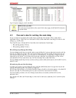
Fig. 14: Query of input channel information, with timestamp
• In Fig.
Query of input channel information, with timestamp
the rising and the falling edge of pulse A is
picked up as event with timestamp and transferred to the controller during the EtherCAT cycle. The
time resolution is 1 ns here – an ‘infinitely’ fine time resolution in mechanical terms. The EL1252 can
“only” store one falling and one rising edge per cycle – if several edge changes occur, e.g. a rising
edge of pulse C, the first or last event is stored, depending on the configuration (see
EL1252
documentation
).
In summary, the
oversampling
and
timestamp
procedures provide a significantly finer image of the
machine sequence than
standard sampling
of the digital input.
Procedure for sampling digital outputs
The principles described above can be transferred to digital outputs accordingly.
•
Standard sampling
A frame-triggered standard output can only switch with the time of each EtherCAT cycle if it receives a
new target output state:
Fig. 15: Output of output channel information, standard
• In Fig.
Output of output channel information, standard
the number of switching events is limited to the
cycle time and cannot be changed at the actual switching time. For high-speed or high-precision
machines this has a significant effect on the maximum possible production speed and manufacturing
tolerances. The
oversampling
and
timestamp
technologies help here as well.
•
Oversampling
The controller calculates the array of digital 0/1 output data in advance and sends it to the output
channel. This successively clocks out the target output states in the fixed microcycle.


