Commissioning
EL125x, EL2258
178
Version: 2.5
6.8.2.1.4
Output data
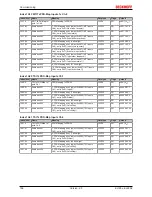
Index 7pp1 MTO outputs (for 00 ≤ pp ≤ 07; Ch. 1 to Ch. 8)
Index (hex) Name
Meaning
Data type
Flags
Default
7pp1:0
MTO outputs
UINT8
RO
0x00 (0
dec
)
7pp1:01
Output buffer reset
Removes all elements from the buffer
Clearing can be achieved through a rising edge or con-
tinuously by applying 1 at this bit. The behavior can be
parameterized via CoE object
0x8pp1:11 [
}
174]
.
BOOLEAN
RO
0x00 (0
dec
)
7pp1:02
Manual output state
This bit can be used to switch the output without using
timestamps.
• Method 1: The CoE object
0x8pp1:02 [
}
174]
("Enable manual operation") is set to TRUE.
Timestamp mode is now switched off, and the
output can only be switched via the bit "Manual
operation state". This is particularly helpful for
the commissioning phase.
• Method 2: Via the bit "Enable manual
operation" (0x7pp1:04) the channel output can
be forced to the value of this object. Timestamp
processing continues in the background. Output
is only reactivated if the bit "Enable manual
operation" is set to 0 again.
BOOLEAN
RO
0x00 (0
dec
)
7pp1:03
Force order
This bit defines how to deal with timestamps that were
placed in the past
(see diagram) [
}
126]
.
BOOLEAN
RO
0x00 (0
dec
)
7pp1:04
Enable manual opera-
tion
See "Manual output state"
(0x7pp1:02) [
}
178]
.
BOOLEAN
RO
0x00 (0
dec
)
7pp1:09
Output order counter
Incrementing this byte indicates to the channel that
new output events can be accepted
UINT8
RO
0x00 (0
dec
)
7pp1:11
No of output events
Number of filled "Output event state" and "Output
event time" objects
UINT8
RO
0x00 (0
dec
)
7pp1:21
Output event state 1
This bit is used to specify which state the output should
assume at the time of "Output event time 1"
BOOLEAN
RO
0x00 (0
dec
)
7pp1:2A
Output event state 10
BOOLEAN
RO
0x00 (0
dec
)
7pp1:41
Output event time 1
Time at which the state described in "Output event
state 1" is to be applied
UINT32
RO
0x00000000
(0
dec
)
7pp1:4A
Output event time 10
UINT32
RO
0x00000000
(0
dec
)
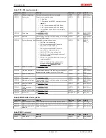
Index 7pp0 MTI outputs (for 08 ≤ pp ≤ 0F; Ch. 1 to Ch. 8)
Index (hex) Name
Meaning
Data type
Flags
Default
7pp0:0
MTI outputs
UINT8
RO
0x00 (0
dec
)
7pp0:01
Input buffer reset
Removes all elements from the buffer
Clearing can be achieved through a rising edge or con-
tinuously by applying 1 at this bit. The behavior can be
parameterized via the CoE object
0x8pp0:11 [
}
175]
("Buffer reset behavior").
BOOLEAN
RO
0x00 (0
dec
)
7pp0:11
Input order counter
This bit indicates to the terminal that the input events
were accepted from the process image and the termi-
nal can copy a new set of input events from the buffer
into the process image during the next cycle
(see buf-
fer mode). [
}
122]
UINT8
RO
0x00 (0
dec
)
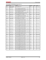
Index 7pp0 TSO Outputs (for 10 ≤ pp ≤ 17; Ch. 1 to Ch. 8)
Index (hex) Name
Meaning
Data type
Flags
Default
7pp0:0
TSO Outputs
UINT8
RO
0x00 (0
dec
)
7pp0:01
Output
Defines whether a rising (1) or falling (0) edge should
be output at the "StartTime"
BOOLEAN
RO
0x00 (0
dec
)
7pp0:11
Activate
A change from 0 to 3 in this byte triggers acceptance
of the order with the current StartTime
UINT8
RO
0x00 (0
dec
)
7pp0:41
StartTime
64 Bit TimeSTamp
UINT64
RO


