background image

Commissioning

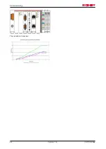
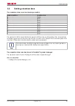
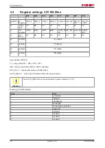
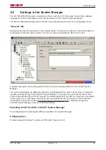
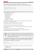
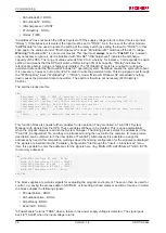
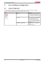
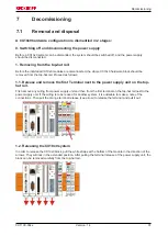
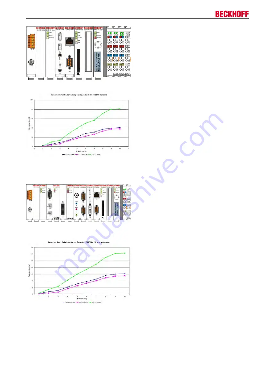
The retention times are:

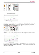
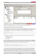
The second test configuration is an Embedded PC with maximal configuration. CX1000-System
(CX1000-0122) with system interfaces N001 (2x USB, DIV), N002 (2x RS232), N003 (Audio), M200 (IP-Link-
Master) und M319 (Profibus-Master). A keyboard with a hub and a mass storage device are connected to
the USB ports as load. The system configuration is shown below.

The light bus is shorted by a fiber optic cable. The PROFI bus master connection is connected to a BK3100
with terminals. The retention times are measured in relation to switch setting.

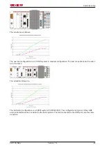
The third test configuration consists of a CX1020-System (CX1020-0120). The configuration is typical. Only
the system interface N010 is connected to the basic module. The terminal bus is an E-bus. One digital output
terminal is connected to the bus.

CX1100-09xx

22

Version: 1.4

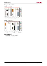
Summary of Contents for CX1100-09 Series

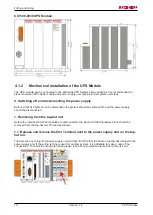
Page 1: ...Hardware Documentation CX1100 09xx UPS for Embedded PCs CX10x0 1 4 2015 07 02 Version Date...

Page 2: ......

Page 3: ...nsport 13 3 1 Unpacking installation and transport 13 4 Fitting and wiring 14 4 1 Mechanical assembly 14 4 1 1 Dimensions 14 4 1 2 Mechanical installation of the UPS Module 16 5 Commissioning 19 5 1 C...

Page 4: ...s in this documentation Trademarks Beckhoff TwinCAT EtherCAT Safety over EtherCAT TwinSAFE XFC and XTS are registered trademarks of and licensed by Beckhoff Automation GmbH Other designations used in...

Page 5: ...umentation the following symbols are used with an accompanying safety instruction or note The safety instructions must be read carefully and followed without fail DANGER Serious risk of injury Failure...

Page 6: ...for charge corrected 1 1 annotations to usage of CX1100 0900 and CX1020 1 0 released version 0 4 revision of discharge graphs licenses added 0 3 resorting small corrections 0 2 revised version 0 1 pre...

Page 7: ...retention time the machine or process can be transferred into a defined state and the operating system can be shut down The retention time can be set via a rotary switch or via software The use of sta...

Page 8: ...Product overview Setup of UPS module sample configuration1 sample configuration 2 Also see about this 2 CX1100 09xx Connections 10 CX1100 09xx 8 Version 1 4...

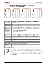
Page 9: ...ax power consumption 2 W Dimensions W x H x D 57 mm x 100 mm x 91 mm 76 mm x 100 mm x 91 mm 95 mm x 100mm x 91 mm 95 mm x 100mm x 91 mm weight app 345 g app 465 g app 617 g app 650 g Operating tempera...

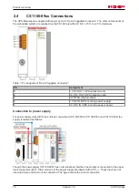
Page 10: ...WR FAIL digital output 2 0 V DC IN UPS incoming power supply 1 24 V DC IN UPS incoming power supply Connection to power supply For power supply units with K bus E bus connection CX1100 0002 CX1100 000...

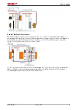
Page 11: ...o be connected seperaty This depends on the terminal bus load The Power Fail connection should be connected to a digital input terminal see picture below In case of power failure the UPS module rises...

Page 12: ...t part on the scope CX System CX1100 0900 CX1100 0910 CX1100 0920 CX1100 0930 CX9000 with WINDOWS CE yes yes yes yes CX9010 with WINDOWS CE yes yes yes yes CX1000 with WINDOWS CE yes yes yes yes CX100...

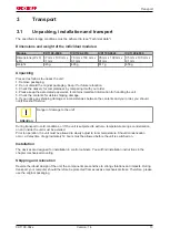
Page 13: ...you notice any shipping damage or inconsistencies between the contents and your order you should notify Beckhoff Service Attention Danger of damage to the unit During transport in cold conditions or i...

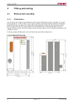
Page 14: ...s and fieldbus interfaces have to be provided The overall width of the application is made up of the individual modules With a height of 100 mm the module dimensions exactly match those of the Beckhof...

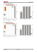
Page 15: ...Fitting and wiring CX1100 0910 UPS Module CX1100 0920 UPS Module CX1100 09xx 15 Version 1 4...

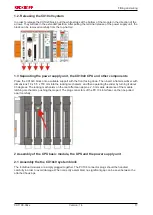
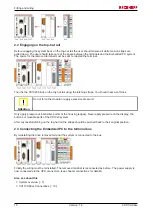
Page 16: ...e disconnected 1 Removing from the top hat rail Before the individual CX10x0 modules are disconnected the whole CX1020 hardware block should be removed from the top hat rail Proceed as follows 1 1 Rel...

Page 17: ...screwdriver with dimensions 1 0 x 5 5 x 150 mm into the locking mechanism and then operating the slider by turning it about 90 degrees The locking mechanism on the rear affects an approx 2 3 mm wide c...

Page 18: ...xcessive pressure Only apply pressure at insensitive points of the housing edges Never apply pressure on the display the buttons or movable parts of the CX10x0 system After successful latching on the...

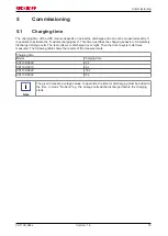
Page 19: ...age cells The test units were discharged over night Then the time to system start was measured The following table shows the results of the measurements Charging time Model Charging time CX1100 0900 4...

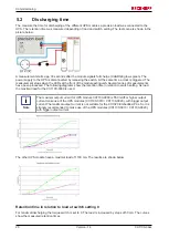
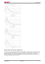
Page 20: ...following diagrams show the retention time in relation to switch setting As load the maximal load for the CX1100 0900 is used Note The maximal output current for UPS module CX1100 0900 is 550 mA For h...

Page 21: ...relation to switch setting The first test configuration is a CX1000 System CX1000 0111 with typical configuration Only the system interface N001 is connected to the basic system The K bus is supplied...

Page 22: ...he USB ports as load The system configuration is shown below The light bus is shorted by a fiber optic cable The PROFI bus master connection is connected to a BK3100 with terminals The retention times...

Page 23: ...e test connections are the same as in the test 2 The retentions times are The last tested configuration is a CX900 system CX9000 0002 The configuration is typical Video USB and serial interfaces are c...

Page 24: ...Commissioning The retention times are CX1100 09xx 24 Version 1 4...

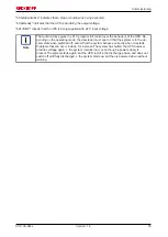
Page 25: ...or some minutes The time can be reduced if the connected system shuts down fast If the system shuts down fast the restart can be accelerated Note The retention time should last longer than system shut...

Page 26: ...er 0 C ASCII 5 identifier 1 X ASCII 6 identifier 2 11 DEC 7 identifier 3 90 DEC base address 0D1010 C charge state 0 00h 100 FFh IRQ binary coded IRQ number 0000 disabled DIP_DIS 1 disable DIP switch...

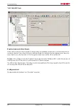
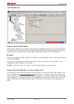
Page 27: ...for the TwinCAT System Manager There are fundamentally two different methods of controlling the UPS module The first way is to make the operating settings directly in the TwinCAT System Manager In thi...

Page 28: ...short periods 10s the system shuts down and the CX is switched off Problem If the voltage returns after TwinCAT has stopped but while Windows XPe is still in the process of shutting down the CX remai...

Page 29: ...soon as the UPS is fully charged again the CX switches on once more Problem The CX10x0 boots in every case even when power failures are extremely short Using the System Manager to set the retention t...

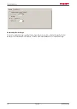
Page 30: ...ettings Once all the desired settings have been made the configuration must be activated through the System Manager You will find further explanations in the documentation for the TwinCAT System Manag...

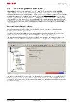
Page 31: ...ther details are given below First the settings of the System Manager are described NecessarySystem Manager settings Everything must be set to OFF In other words on the CX1190 UPS tab neither Enable A...

Page 32: ...LC off The permitted entries here are between 0 and 10 seconds The boolean expression bDIPDisable allows the setting of the rotary switch on the UPS to be ignored If the value is TRUE then the value s...

Page 33: ...UE when a failure in the supply voltage has been detected and the retention time has not yet elapsed tTimeUntilShutdown indicates the retention time remaining until shutdown eUpsState displays the sta...

Page 34: ...nly TRUE if switching off is desired everything OFF bShutdown5V FALSE DO NOT USE reserved function iDischargeLevel 3 Values from 0 1 9 bTcStopOnly TRUE Under WINDOWS CE in order to save the persistent...

Page 35: ...ating mode the developer must see to it that the system is in the de sired state when switched off and or that the system behaves correctly when it restarts Problems that can occur include for instanc...

Page 36: ...ates and their meaning Display LED Meaning 24 V IN power supply in The LED glows green if input power supply 21 5 V is connected otherwise it glows red 24 V OUT power supply out The LED glows green if...

Page 37: ...l next to the power supply unit on the top hat rail First remove any wiring from power supply unit and then from the first terminal on the top hat rail next to the power supply unit If the wiring is t...

Page 38: ...anism pushing them apart The plug connectors of the PC 104 interface can then be pulled apart carefully Only modules CPU fieldbus connections and UPS modules that can be separated non destructively fe...

Page 39: ...its are designed to provide reasonable protection against harmful interference when the equipment is operated in a commercial environment This equipment generates uses and can radiate radio frequency...

Page 40: ...quarters Beckhoff Automation GmbH Co KG Huelshorstweg 20 33415 Verl Germany Phone 49 0 5246 963 0 Fax 49 0 5246 963 198 e mail info beckhoff com Beckhoff Support Support offers you comprehensive techn...

Reviews: