Product overview
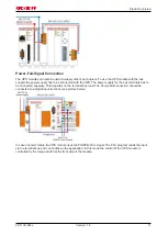
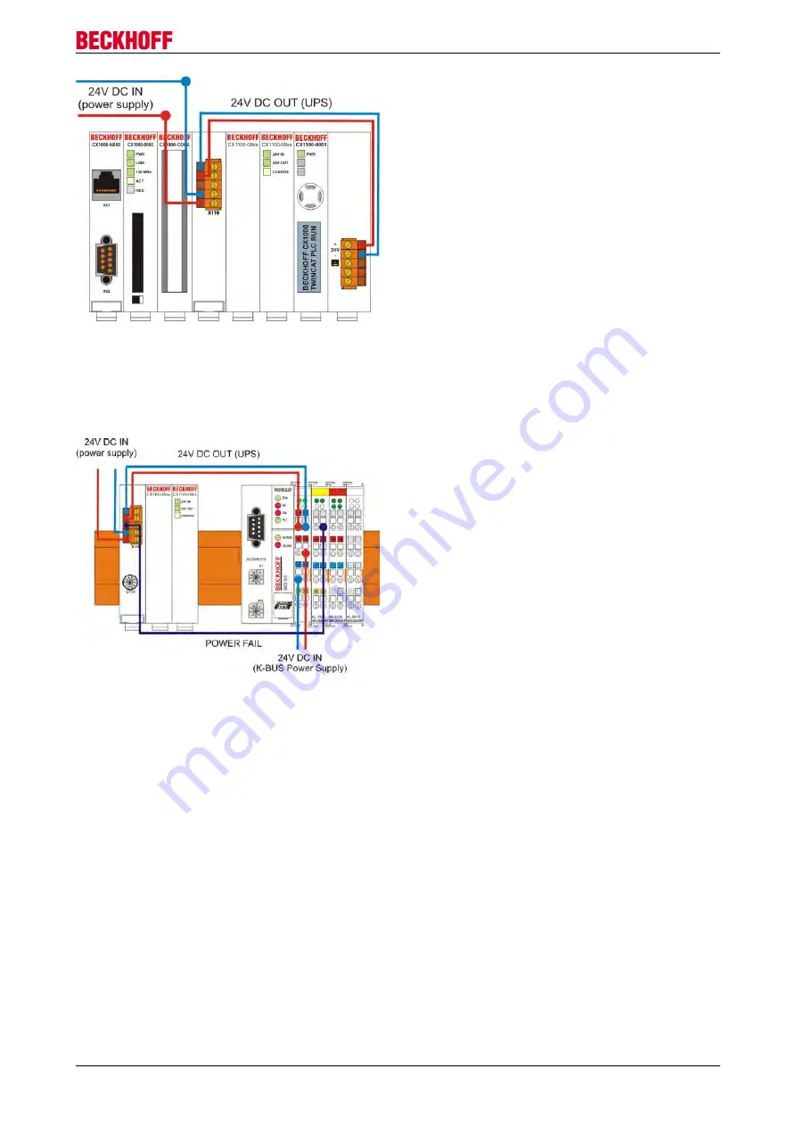
Power-Fail-Signal Connection
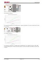
The UPS modules can also be used to supply other bus couplers. To use the UPS module with the bus
coupler the power supply has to be connected with the UPS. The power supply for the bus terminals has to
be connected seperaty. This depends on the terminal bus load. The Power-Fail connection should be
connected to a digital input terminal. (see picture below)
In case of power failure the UPS module rises the POWER-FAIL signal. The PLC program reads the input
via the terminal bus and can shutdown the application. In this mode the control of the UPS module is
controlled by the torque switch at the front side of the module.
CX1100-09xx
11
Version: 1.4
Summary of Contents for CX1100-09 Series
Page 1: ...Hardware Documentation CX1100 09xx UPS for Embedded PCs CX10x0 1 4 2015 07 02 Version Date...
Page 2: ......
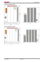
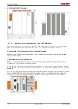
Page 15: ...Fitting and wiring CX1100 0910 UPS Module CX1100 0920 UPS Module CX1100 09xx 15 Version 1 4...
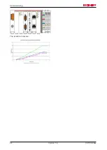
Page 24: ...Commissioning The retention times are CX1100 09xx 24 Version 1 4...


