Fitting and wiring
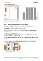
1.2. Releasing the CX10x0 system
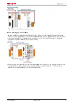
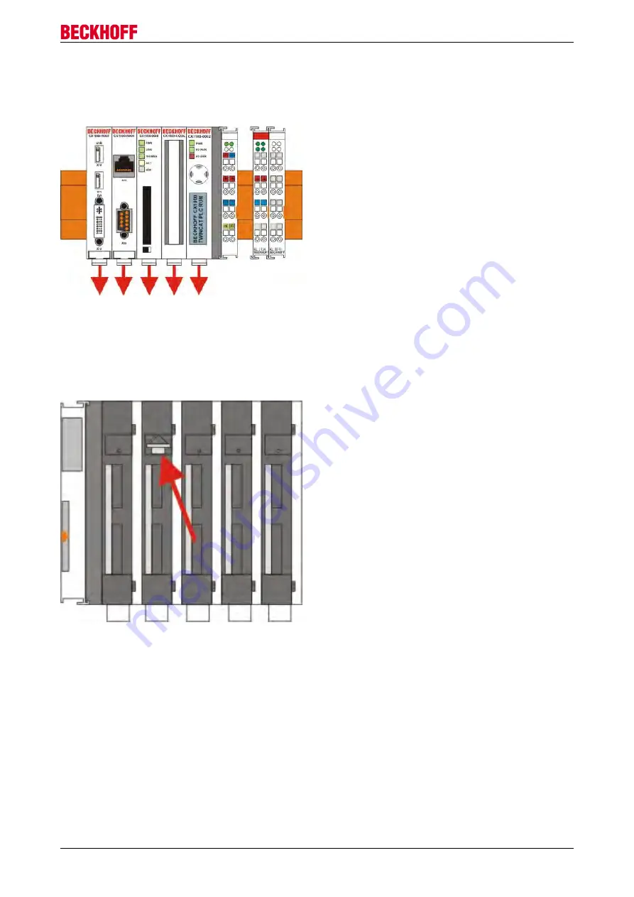
In order to release the CX10x0 block, pull the white straps at the bottom of the module in the direction of the
arrows. They will lock in the extended position. After pulling the terminal release of the power supply unit, the
block can be removed
carefully
from the top-hat rail.
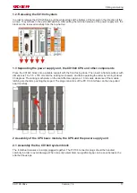
1.3 Separating the power supply unit, the CX10x0 CPU and other components
Place the CX10x0 block onto a suitable support with the front facing down. Then insert a flat screwdriver with
dimensions 1.0 x 5.5 x 150 mm into the locking mechanism, and then operating the slider by turning it about
90 degrees. The locking mechanism on the rear affects an approx. 2-3 mm wide clearance of the module
latching mechanism, pushing them apart. The plug connectors of the PC 104 interface can then be pulled
apart carefully.
2 Assembly of the CPU basic module, the UPS and the power supply unit
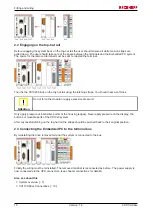
2.1 Assembly the the CX10x0 system block
The individual modules are simply plugged together. The PC104 connector plugs should be handled
carefully in order to avoid damage. When correctly assembled, no significant gap can be seen between the
attached housings.
CX1100-09xx
17
Version: 1.4
Summary of Contents for CX1100-09 Series
Page 1: ...Hardware Documentation CX1100 09xx UPS for Embedded PCs CX10x0 1 4 2015 07 02 Version Date...
Page 2: ......
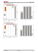
Page 15: ...Fitting and wiring CX1100 0910 UPS Module CX1100 0920 UPS Module CX1100 09xx 15 Version 1 4...
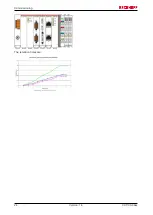
Page 24: ...Commissioning The retention times are CX1100 09xx 24 Version 1 4...

