Commissioning
5.2
Discharging time
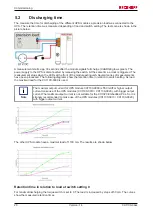
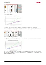
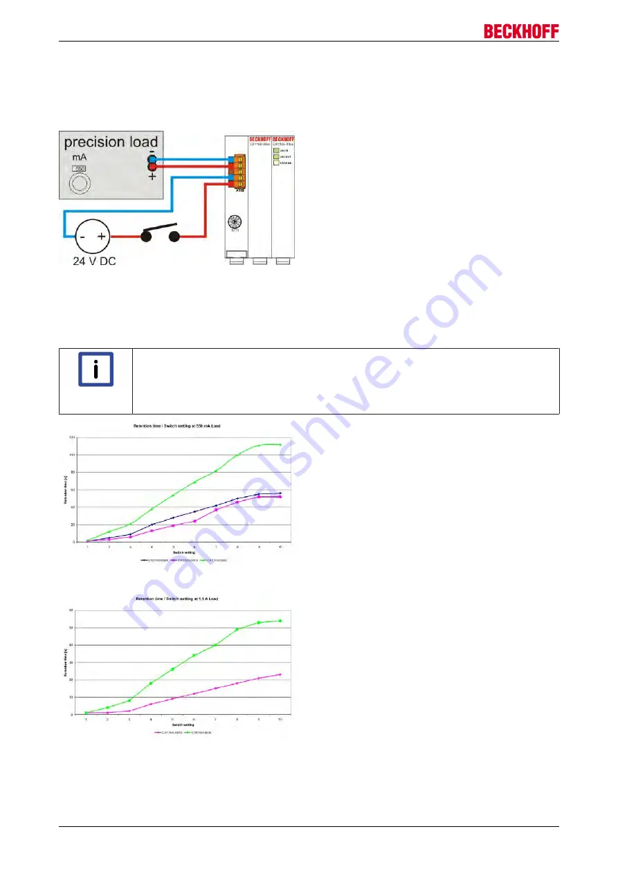
The measure the time for discharging of the different UPS modules a precision load was connected to the
UPS. The retention time was measured depending of load and switch setting. The test scene is shown in the
picture below.
A measurement starts app. 30 seconds after the module signals full charge (CHARGE glows green). The
power supply to the UPS is disconnected by releasing the switch. At the same time a clock is triggered. The
measurement stops when the LEDs at the front of the module extinguish. Several series of measurements
have been processed. The following diagrams show the retention time in relation to switch setting. As load
the maximal load for the CX1100-0900 is used.
Note
The maximal output current for UPS module CX1100-0900 is 550 mA!For higher output
current make use of the UPS modules (CX1100-0910 / CX1100-0920), with bigger output
current.The maximal output current is not suitable for the CX1020 Embedded PCs. So it is
strongly recommended to make use of the UPS modules (CX1100-0910 / CX1100-0920),
with bigger output current.
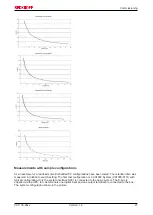
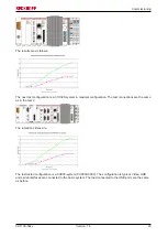
The other UPS module have a maximal load of 1100 mA. The results are shown below.
Retention time in relation to load at switch setting 0
For maximal discharging the torque switch is set to 0. The load is increased by steps of 50 mA. The curves
show the measured retention times.
CX1100-09xx
20
Version: 1.4
Summary of Contents for CX1100-09 Series
Page 1: ...Hardware Documentation CX1100 09xx UPS for Embedded PCs CX10x0 1 4 2015 07 02 Version Date...
Page 2: ......
Page 15: ...Fitting and wiring CX1100 0910 UPS Module CX1100 0920 UPS Module CX1100 09xx 15 Version 1 4...
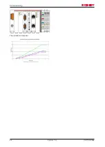
Page 24: ...Commissioning The retention times are CX1100 09xx 24 Version 1 4...

