


80-4280-10, Rev. 4
47
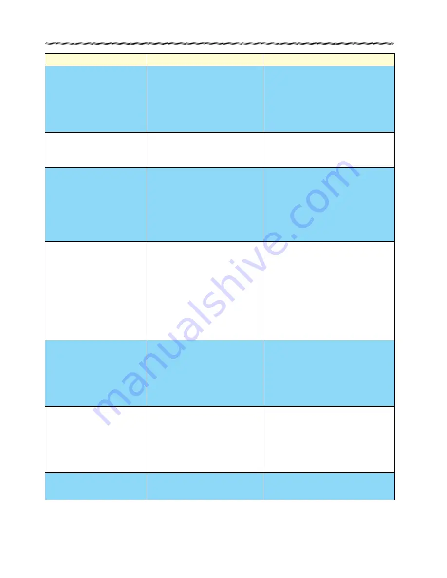
Conditions
Possible Causes
Corrections
1. No DCM-2 LEDs are
illuminated.
a. No power is applied to the actuator.
b. Incorrect power is applied to the
actuator.
c. Main power fuse/breaker is blown.
d. DCM-2 malfunction.
a. Apply operating voltage to the operating
voltage terminals.
b. Verify correct voltage on actuator
nameplate and ensure that it is applied
at the operating voltage terminals.
c. Verify fuse/breaker integrity. Replace/
reset if blown. Find cause of short circuit.
d. Replace DCM-2.
2. STAT LED is illuminated.
a. A status alarm is active.
a. Check the status indication LEDs on
the pushbutton interface of the DCM-2.
Continue troubleshooting based on the
LEDs that are illuminated.
3. DEMAND LED is illuminated. a. No loop-power is present.
b. No Demand signal.
c. Applied Demand signal is outside
of configured range.
d. Polarity of applied signal wires is
reversed.
a. Restore DC voltage for 2-wire feedback.
b. Apply a Demand signal to terminals
14 (–) & 15 (+).
c. Confirm Demand signal value via HART or
by measuring DC voltage across DCM-2
test points TP3(+) & TP2(–). Should be
1–5 volts for 4–20 mA applied signal.
d. Correct the polarity of the applied control
signal wires on terminals 14 (–) & 15 (+).
4. POSITION LED is illuminated. a. Position signal voltage generated
by CPS-4 read by the DCM-2 is
outside of the configured range.
b. CPS-4 malfunction.
c. DCM-2 malfunction.
a. Using the HART communicator check
the Position Sensor Setup menu to verify
the Present CPS voltage falls within the
configured CPS Zero% and Span (typical
range 1–5 volts); OR measure DC
voltage between DCM-2 test points TP4
(+) and TP1 (–) to verify Present CPS
voltage. If the voltage is outside of 1–5
volts, recalibrate the CPS-4 or replace
the control end.
b. Replace control end.
c. Replace DCM-2.
5. TORQUE LED is illuminated. a.
Torque exceeding configured limit
(typically over 105% of rated torque)
is being applied to the output shaft.
b. Torque Null and Torque Constant
values are not set correctly.
c. Torque cable is not connected to
DCM-2.
a. Eliminate cause of excessive torque
(i.e., binding damper, improper linkage,
etc.).
b. Locate Torque Null and Constant values
inside DCM compartment and set via
HART or Serial port.
c. Reconnect torque cable to DCM-2.
6. STALL LED is illuminated.
a. Actuator has stalled—unable to
achieve desired position within the
configured “STALL TIME”.
b. The configured stall time is less
than the configured Max Travel
Time.
a. Eliminate the obstruction and reset
the stall by reversing direction on your
Demand signal, cycling the power, or
issuing the stall reset from HART or
Serial command.
b. Configure the stall time to exceed the
Max Travel Time via HART or Serial
command.
7. TEMP F LED is illuminated. a. The measured temperature at the
DCM-2 is outside of the normal
operating range of -40° to 185° F.
a. Protect the actuator from the extreme
temperatures below or above the
operating range to eliminate the alarm.


