


80-4280-10, Rev. 4
12
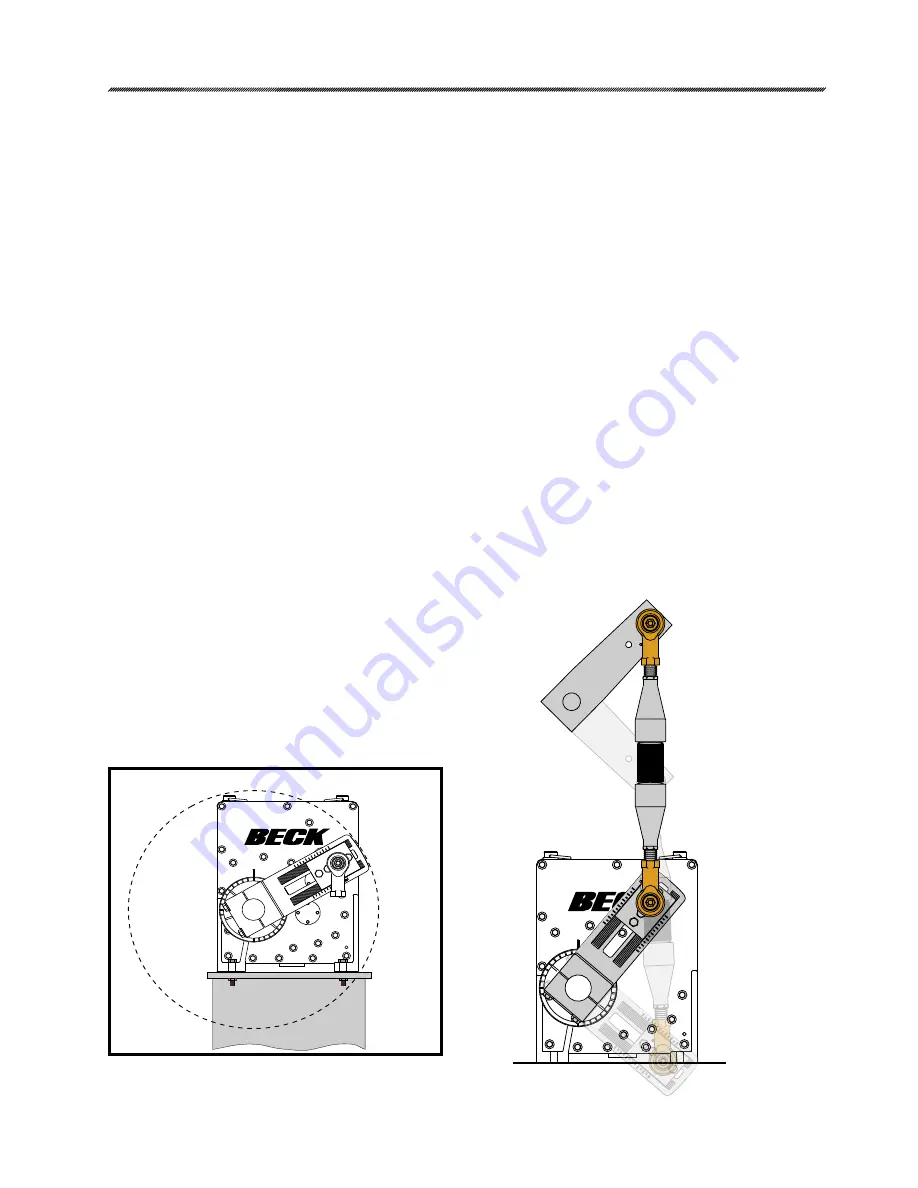
PARALLEL LINKAGE ARRANGEMENT
INSTALLATION
Mechanical
4
10
6
8
8
10
4
6
2
2
0
CLOSED
OPEN
OPEN
CLOSED
MOUNTING THE DRIVE
Once the design installation conditions have
been considered, you should mount the actuator
to the mounting base.
Beck Group 22 actuators must be installed
feet down. If mounting near obstructions such as
pipes or beams, take into consideration access
to the field wiring terminals and the output shaft.
Refer to the outline dimension drawings for the
clearance necessary to remove covers.
Before the actuator is bolted into place, the
mounting surface must be shimmed for flatness
to within 0.020 inches. Each shim must support
at least 75% of the mounting foot surface area
(recommended shim size is 4 square inches or
larger). Improper shimming or mounting can
damage mounting feet.
If the actuator is to be bolted to a mounting
plate, the plate must be rigid must not yield to the
stresses created from operating the actuator. If
the mounting plate is not rigid or the mounting
bolts are not sufficiently tightened, damage to the
actuator housing could result. A rigid, vibration-
free surface will generally prolong the life of the
actuator’s components. The mounting plate
should be at least as thick as the diameter of the
mounting bolts.
Mounting bolts should be 7/8”-9. The bolts
should be hex head steel, zinc plated (HHSZP)
Grade 5 or better. The bolts should be torqued
appropriately for the application.
4
10
6
8
10
4
6
2
0
360° Crank Arm Rotation
LINKAGE REQUIREMENTS
For best results, the linkage should be
designed in advance. In most applications, the
best control will result when the linkage is adjusted
so that the full 100° travel of the Beck actuator
shaft is used, even though the driven lever may
travel less than 100°. The general requirements
for a good linkage are:
1. It must be rigid enough to carry the link thrust
without bending or deforming.
2. It must have a built-in means of adjustment so
that the length of the connecting link can be
changed a small amount.
3. Rod end bearings, similar to those furnished
on the Beck crank arm, should be used at
both ends of the connecting link. This type of
device permits small angular misalignments
and helps prevent binding of the linkage.
4. The Beck crank arm radius must be calculated
so that the arm will move through a 100° arc and
the driven lever will move through its correct arc.
5. The actuator and driven shafts must be
parallel and the linkage should be in a plane
perpendicular to the shafts. See the example
of a parallel linkage arrangement below.


