


80-4280-10, Rev. 4
CONFIGURATION / CALIBRATION
26
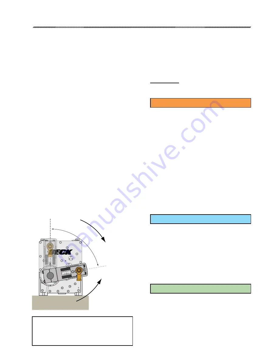
Figure 4.
ROTATION DIRECTION
Rotation direction refers to the direction the
output shaft of the actuator rotates in response to
an increasing Demand input signal. The rotation is
either clockwise (CW) or counterclockwise (CCW)
as shown in the figure below. The rotation of the
driven load (i.e. damper lever arm) determines the
actuator rotation suitable for an application.
Unless otherwise specified at the time of
the order, Group 22 actuators are set for CW
rotation, which means that the output shaft rotates
clockwise in response to an increasing Demand
signal. The CPS rotation is also normally set
to CW, which means it provides an increasing
Position feedback signal to the actuator’s DCM
when the output shaft rotates clockwise. The CPS
setting may need to be changed if reversing the
direction of actuator rotation.
There are two procedures for changing direction
of actuator travel outlined below. The first is a simple
method that requires no special adjustments to the
CPS-4 or no change to the CPS rotation setting in
the DCM configuration. When using this method,
the external feedback signal will be inversely
proportional to the Demand input signal after the
change is complete. For example, given a 4–20 mA
Demand input, the corresponding 2-wire Position
feedback signal from the CPS-4 will be 20–4 mA.
The second procedure is necessary if it is
desirable to keep the Position feedback signal from
the CPS-4 direct-acting with respect to the Demand
input; i.e., a 4–20 mA Demand signal will result
in a 4–20 mA feedback. This procedure is more
involved because it requires changing the CPS
rotation setting in the DCM and also making some
mechanical calibration adjustments to the CPS-4.
Procedure 1
Simply change direction of travel using any of
the three standard methods below.
PUSHBUTTONS
method
1. Position the actuator to the desired 0%
position.
2. Press and hold the “CALIBRATE” and “POS
0%” pushbuttons on the DCM’s local interface
panel until the “ACKNOWLEDGE” LED lights.
OR
1. Position the actuator to the desired 100%
position.
2. Press and hold the “CALIBRATE” and “POS
100%” pushbuttons on the DCM’s local
interface panel until the “ACKNOWLEDGE”
LED lights.
*If the “ACKNOWLEDGE” LED does not light, but
the “POSITION” LED does light, the signal is out
of acceptable range and was not accepted by the
DCM.
HART
method
HART DD Menu Location: MENU 5A
Functions> Configuration> General Setup
Command: actuator Dir
Selections:
CW Incr
- select if the desired output shaft rotation
is clockwise on increasing Demand signal.
CCW Incr
- select if the desired output shaft
rotation is counter-clockwise on increasing
Demand signal.
SERIAL
command method
Command: drvdir
Arguments:
0
: CW - select if the desired output shaft rotation is
clockwise on increasing Demand signal.
1
: CCW - select if the desired output shaft rotation
is counter-clockwise on increasing Demand
signal.
(e.g.:
“drvdir 0” to select clockwise rotation on
increasing Demand signal.)
2
0
4
10
8
6
2
0
4
8
10
4
80°
CW ROTATION
0% POSITION
FULLY CLOSED
100% POSITION
FULLY OPENED
CCW ROTATION
NOTE: The crank arm in the figure above
may be adjusted to any start angle. The
orientation and rotation shown here has
been randomly selected for the purpose of
this example.


