– 163 –
CXD3068Q
§ 5-8. TRK (Tracking) and SLD (Sled) Servo Control
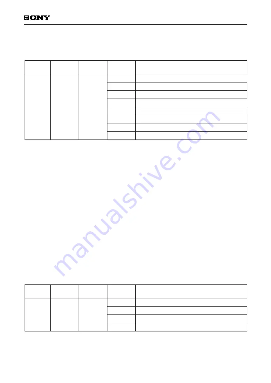
The TRK and SLD servos are controlled by the 8-bit command $2X. (See Table 5-9.)
When the upper 4 bits of the serial data are 2 (Hex), TZC is output to the SENS pin.
Register
name
Command
D23 to D20
D19 to D16
TRACKING SERVO OFF
TRACKING SERVO ON
FORWARD TRACK JUMP
REVERSE TRACK JUMP
SLED SERVO OFF
SLED SERVO ON
FORWARD SLED MOVE
REVERSE SLED MOVE
0 0 1 0
TRACKING
MODE
2
Table 5-9.
TRK Servo
The TRK JUMP (track jump) level can be set with 6 bits (D13 to D8) of $36.
In addition, when the TRK servo is on and D17 of $1 is set to 1, the TRK servo filter switches to gain-up mode.
The filter also switches to gain-up mode when the LOCK signal goes low or when vibration is detected with the
anti-shock circuit (described hereafter) enabled.
The CXD3068Q has 2 types of gain-up filter structures in TRK gain-up mode which can be selected by setting
D16 of $1. (See Table 5-17.)
SLD Servo
The SLD MOV (sled move) output, composed of a basic value from 6 bits (D13 to D8) of $37, is determined by
multiplying this value by 1
×
, 2
×
, 3
×
, or 4
×
magnification set using D17 and D16 when D18 = D19 = 0 is set with
$3. (See Table 5-10.)
SLD MOV must be performed continuously for 50µs or more. In addition, if the LOCK input signal goes low
when the SLD servo is on, the SLD servo turns off.
Note) When the LOCK signal is low, the TRK servo switches to gain-up mode and the SLD servo is turned off.
These operations are disabled by setting D6 (LKSW) of $38 to 1.
Register
name
Command
D23 to D20
D19 to D16
0 0 0 0
0 0 0 1
0 0 1 0
0 0 1 1
SLED KICK LEVEL (basic value
× ±
1)
SLED KICK LEVEL (basic value
× ±
2)
SLED KICK LEVEL (basic value
× ±
3)
SLED KICK LEVEL (basic value
× ±
4)
0 0 1 1
SELECT
3
Table 5-10.
∗
: Don't care
0 0
∗ ∗
0 1
∗ ∗
1 0
∗ ∗
1 1
∗ ∗
∗ ∗
0 0
∗ ∗
0 1
∗ ∗
1 0
∗ ∗
1 1
Summary of Contents for PV420S
Page 1: ...SERVICE MANUAL PV420S WWW BBK RU ...
Page 72: ... 69 CXD3068Q Block Diagram ...
Page 73: ... 70 CXD3068Q Pin Configuration ...
Page 122: ... 119 CXD3068Q Timing Chart 1 3 ...
Page 123: ... 120 CXD3068Q Timing Chart 1 4 ...
Page 124: ... 121 CXD3068Q Timing Chart 1 5 ...
Page 129: ... 126 CXD3068Q Timing Chart 2 1 ...
Page 130: ... 127 CXD3068Q Block Diagram 2 2 ...
Page 131: ... 128 CXD3068Q Timing Chart 2 3 ...
Page 134: ... 131 CXD3068Q Timing Chart 2 6 ...
Page 138: ... 135 CXD3068Q VCO C Mode Fig 3 3 Access Flow Chart Using VCO Control ...
Page 140: ... 137 CXD3068Q Block Diagram 4 1 ...
Page 143: ... 140 CXD3068Q Timing Chart 4 4 ...
Page 147: ... 144 CXD3068Q Fig 4 6 a Auto Focus Flow Chart Fig 4 6 b Auto Focus Timing Chart ...
Page 148: ... 145 CXD3068Q Fig 4 7 a 1 Track Jump Flow Chart Fig 4 7 b 1 Track Jump Timing Chart ...
Page 149: ... 146 CXD3068Q Fig 4 8 a 10 Track Jump Flow Chart Fig 4 8 b 10 Track Jump Timing Chart ...
Page 150: ... 147 CXD3068Q Fig 4 9 a 2N Track Jump Flow Chart Fig 4 9 b 2N Track Jump Timing Chart ...
Page 151: ... 148 CXD3068Q Fig 4 10 a Fine Search Flow Chart Fig 4 10 b Fine Search Timing Chart ...
Page 152: ... 149 CXD3068Q Fig 4 11 a M Track Move Flow Chart Fig 4 11 b M Track Move Timing Chart ...
Page 157: ... 154 CXD3068Q Fig 4 15 CD TEXT Data Timing Chart ...
Page 162: ... 159 CXD3068Q Fig 5 3a Fig 5 3b ...
Page 196: ... 193 CXD3068Q Description of Data Readout ...
Page 200: ... 197 CXD3068Q ...
Page 201: ... 198 CXD3068Q ...
Page 202: ... 199 CXD3068Q ...
Page 207: ... 204 CXD3068Q Package Outline Unit mm ...
Page 208: ...This data sheet has been made from recycled paper to help protect the environment 205 ...


