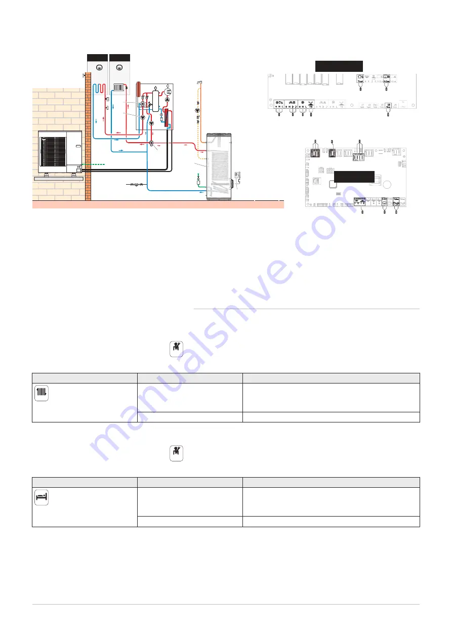
Fig.14
Connect CIRC A0 to EHC–05 and CIRC B1 to SCB-10
X23 X19
X25
EHC-05
4
3
M
M
θ
9
13
5
7
6
11
8
12
10
14
MW-1001775-1
SCB-10
13
12
5
9
7
6
8
11
10
3
3
4
14
CIRCB1 CIRCA0
3 X19: Control signal for the immersion heater, used to
control the immersion heater on the reversal valve kit
4 X25: Reversal valve from the reversal valve kit: A0/
domestic hot water circuit
5 Flow sensor – B1 circuit
6 Three-way valve – B1 circuit
7 Power supply for the B1 circuit pump
8 Domestic hot water recirculating pump
9 Safety thermostat for underfloor heating flow
10 X12 R-Bus: Thermostat connected to A0 circuit
11 X28 Tdhw2: domestic hot water sensor
12 Thermostat connected to B1 circuit
13 Outdoor temperature sensor
14 X23: Outdoor unit bus connection
5.1.2
Applying the parameters
1. To configure the back-up boiler: on first start-up or after resetting the
factory settings, set the CN1 and CN2 parameters according to the
information on the data plate and the outdoor unit output.
2. Configure and check the parameters of the A0 circuit.
Tab.15
Access
Parameter
Adjustment required
21.7
CIRCA0> Parameters,
counters, signals > Parameters
MaxZoneTFlowSetpoint (CP000) Maximum Flow Temperature setpoint zone: 75 °C
Adjust the temperature as required
Zone Function (CP020)
Functionality of the zone: Direct
3. Set the heating curve on the A0 circuit to a gradient of 1.5. Adapt the
values of the heating curve in order to obtain optimum comfort.
4. Configure the parameters for the B1 circuit.
Tab.16
Access
Parameter
Adjustment required
19.8
CIRCB1 > Parameters,
counters, signals > Parameters
MaxZoneTFlowSetpoint (CP000) Maximum Flow Temperature setpoint zone: 40 °C
Adjust the temperature according to need
Zone Function (CP020)
Functionality of the zone: Mixing Circuit
5. Set the heating curve on the B1 circuit with a gradient between 0.4
and 0.7. Adapt the values of the heating curve in order to obtain
optimum comfort.
On
On
5 Connecting diagrams and configuration
7762758 - v05 - 19082020
23


