background image


30


Operating Manual for 

Bauer Separator Compact


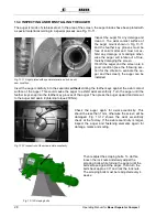
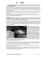
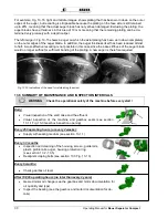
For example, Fig. 13-15, right and middle images, shows plating that has been worn down on the outer 
edges of the auger, but recoating is still possible because the plating on the face side is still retained 
up to 20%, meaning that the actual auger blade has not yet been damaged. Excluding the plating, the 
auger blades have a thickness in this area of 10 mm, meaning that the remaining plating can be de-
termined very precisely with a depth caliper. 
 
The left image in Fig. 13-15 shows a auger on which the axial plating has been worn down completely 
on the outer edges of the auger blade. In addition, the auger thickness itself has been reduced almost 
to half. A cost-effective recoating is not possible in this case since the base stiffness of the auger blade 
would no longer suffice for sufficient bonding of the plating. A new auger is therefore required. 


13.6  SUMMARY OF MAINTENANCE AND INSPECTION INTERVALS 


Check the operational safety of the machine before every start ! 


Daily:   

  Visual inspection of the solid cake and the effluent


  Visual  inspection  of  the  machine  and  gearbox  seals  (see  section 

13.1.1 Fig. 13-3 Gearbox inspection opening)


Every 250 operating hours (or every 2 weeks):  

  Supply with sealing medium (see section 13.1.1)


Every 1-3 months  

  Inspection and cleaning of the housing, screen, guide rails,  

plastic profile rails, auger, housing protection ring  
(see section 13.2 - 13.5) 

  Readjust scraping bolts (see section 13.3 Fig. 13-13) 


Every 6 months: 

  Check gearbox oil level 

 
After 10,000 operating hours (no later than every 2 years) 

  Geared motor oil change (see the gearbox and motor documentation for 

oil quantity and type) 

  Inspect the bearing (see the gearbox and motor documentation for de-

tails) 


Fig. 13-15 Indications of the need for refurbishing the screw 


WARNING 


Summary of Contents for Separator Compact

Page 1: ...OPERATING MANUAL for Separator Compact Version I 2014 ...

Page 2: ...ars to come The content of this operating manual is the intellectual property of the company BAUER GesmbH and or its supplier companies The available information may only be used in connection with the cre ation of specification compliant documents in the course of an order from the BAUER company Without express written permission from the BAUER company no reproduction or sharing of this operating...

Page 3: ...mail sales bauer at com www bauer at com Owner or operator Name Address Tel Fax Note Make a note of the type designation and serial number of your separator and its accessories Include these numbers along with all contact with your dealer 1 It is very important to include with all guarantee claims and all correspondence related with this ma chine the entire serial number group including all letter...

Page 4: ...ation Signs 12 4 5 1 Information on the Separator Type Plate 12 4 5 2 Information Signs 12 4 6 Separator Technical Data 12 4 7 Setup and Assembly 13 4 8 Complete System 14 4 8 1 Inflow Setup 15 4 8 2 Drainage Line 15 5 ELECTRICAL CONNECTION 16 5 1 Setup and Operation of the Motor 17 5 2 Condensate Hole 17 5 3 Installation Without Switch Cabinet 17 6 PREPARATION FOR INITIAL STARTUP 18 7 INITIAL STA...

Page 5: ...ieve 27 13 4 Inspecting and Reinstalling the Screw 28 13 5 Evaluation Criteria for the Screw and Sieve with Regard to Wear and Refurbishing 29 13 6 Summary of Maintenance and Inspection Intervals 30 14 PROBLEMS TROUBLESHOOTING 31 14 1 Principles of a Normal Operating Condition 31 14 2 Troubleshooting 32 15 ACCESSORIES 35 15 1 Separator Control 35 15 1 1 Motor protection circuit breaker F1 35 16 NO...

Page 6: ...ohibitions to protect against serious injury or property damage WARNING Special information on preventing minor injuries or requirements and prohibi tions to prevent damage to the machine NOTE Special instructions to simplify working with the machine or to aid in efficient use of the machine To prevent malfunctions that could directly or indirectly result in serious injuries or property damage it ...

Page 7: ...e used and operated only by persons who are familiar with the sys tem and aware of the hazards involved All relevant rules for accident prevention as well as any other generally accepted rules and regula tions relating to safety occupational medicine and traffic laws must be strictly observed Unauthorized modifications to the machine release the manufacturer from liability for damage re sulting fr...

Page 8: ...ersonnel who are being trained taught instructed or are participating in a general training program may only work on the system under the constant supervision of a person experienced in operation of the system The safety and risk conscious work by the personnel in compliance with the operating manual must be checked at least at certain intervals The personnel assigned to operate the machine may no...

Page 9: ...pected starting of the system It must be noted that a pressed EMERGENCY OFF button does not provide any protection against unau thorized starting of the machine During disassembly and assembly large individual parts and entire assemblies must be carefully fastened and secured to lifting equipment Only suitable lifting equipment and load handling devices with sufficient carrying capacity and no tec...

Page 10: ...e area of the auger while the ma chine is running In handling slurry always remember that the gases produced by the slurry are highly toxic and explosive in combination with oxygen Open flame light checks spark creation and smoking are therefore prohibited When using the retention or alternating retention method special care must be taken in the area of the opened sliding gates to the pre pool bef...

Page 11: ...gravity inside the screen The interior auger transports the pre drained material horizontally toward the solid outlet Along the last section of the transport path the auger presses out additional liquid which escapes the separator through the screen as thin slurry The required contact pressure is applied to the escaping solid by a system consisting of a cap loaded by a weighted lever The solid liq...

Page 12: ...n of the BAUER separator DANGER Work on electrical and electronic components of the system may only be per formed by a trained electrician or otherwise appropriately trained personnel under the guidance and supervision of a trained electrician in accordance with the ap plicable electrical and electronic regulations 4 3 REQUIRED TOOLS Special tools are not required for setting up the separator Stan...

Page 13: ...separator components for the specific application before it is purchased manufactured assembled and shipped 1 2 3 4 6 7 8 9 10 11 12 The precise article numbers of the wearing parts and the organization of the main components can be found in the replacement parts list Item Part Item Part 1 Geared motor 7 Internal brace 2 Sieve housing 8 Weights 3 Press head 9 Housing protection ring 4 Double flap ...

Page 14: ...s The following information signs are located on the BAUER separator Red arrow on the mouth piece indicates the correct rotation direction of the auger shaft Yellow text field on the mouth piece warns of a turning part Yellow warning symbols on the housing shell indicate that turning parts should not be touched Yellow text field on the geared motor indicates the lubrication interval for the sealin...

Page 15: ... the screen for maintenance It must be possible to remove the auger and the screen for regular inspections Width of the setup area No less than 2000 mm Length of the setup area No less than 2900 mm The surrounding clearance around the separator should be at least 1 m Handrail height of the setup area No less than 1000 mm Make sure that the mouth piece and the functioning of the separator can be cl...

Page 16: ...tances to limit the pressure on the separator In this case an overflow is not required The effluent should be disposed of via an open and thereby ventilated drain channel or col lected in a drainage pit and then pumped out in order to avoid generating a suction effect on the separator The ventilation is required be cause otherwise particles are drawn into the screen gap and remain stuck there bloc...

Page 17: ...d for this Connect the overflow line to the top horizontal outlet of the in flow element socket DN100 A tube of DN100 is also required for this A breather pipe or tube must be connected to the vertical con nection of the inflow element socket DN100 This prevents the buildup of negative pressure in the separator if the medium cre ates suction in the return line siphon effect The breather tube shoul...

Page 18: ...eaker that must be set to the rated current shown on the type plate depending on the motor wiring Only motor protection circuit breakers certified according to the following standards may be used IEC UL CSA WARNING Set the motor protection circuit breaker to the correct value never above the max rated current according to the type plate It is recommended that the corresponding electrical control f...

Page 19: ...t provide any protection against unauthorized starting of the machine 5 2 CONDENSATE HOLE We recommend a condensate hole on motors that are subjected to high temperature fluctuations or extreme climatic conditions DANGER A motor protection circuit breaker or a protection device with overload relay must always be installed to protect the motor winding Fuses do not protect the motor from overloads t...

Page 20: ...pose of old oil 8 Check The supply line between the pump and the separator is connected and sealed the over flow line is connected and sealed open discharge into the storage container line for drainage of the separated slurry connected and sealed open discharge into storage container 9 Motor protection circuit breaker set to required rated current after switching on verify the cor rect rotation di...

Page 21: ...ion process continues by a newly formed solid cake made of the separated medium pressing out the starter cake A starter cake should be employed when the solid cake has been removed from the machine for cleaning inspection or mainte nance purposes If the machine is not operated for a prolonged period of time such that the cake has either hardened frozen or become very soft a starter cake is also re...

Page 22: ... determine the dry matter content of the solid phase 7 3 CONFIGURATION TO STABILIZE THE SOLID CAKE 7 3 1 Cake Too Firm Move the weights inward on the arms or remove them entirely If the cake is too firm the separator may clog up after prolonged operation since the cake can no longer be pushed out of the mouthpiece In order for the cake to be ejected more easily the weights can be moved forward sym...

Page 23: ...ng to avoid shooting or clogging due to irregularities But also ensure that the slurry is not stirred up and repumped too often especially for small pre pools causing the slurry consistence to change become smooth up to the point when no solid matter is separated at all As a remedy a buffer container should be situated at the separator inflow that is filled by means of a level control 8 WINTER OPE...

Page 24: ...with a gap width of 0 75 mm the effluent can be introduced to a separator with a gap width of 0 25 mm and so on To determine the possible dry matter content for your application using the separator perform a screen test such as with a screen of gap width 0 50 mm The dry matter content when using the sepa rator will always be higher than your test result since the solids are filtered by the solid c...

Page 25: ...tor breathe somewhat in other words they move up and down a little If the up and down movement of the arms is too large you must increase the contact pressure by increasing the number of the weights or their leverage If the contact pressure becomes too high the solid cake will become too hard see section 14 Problems Troubleshooting 12 TAKING THE SEPARATOR OUT OF OPERATION 1 Switch off the feed pum...

Page 26: ...he attached unit against the inflow housing in order to protect the seals in the attached unit from the medium being separated This can be accomplished with sealing grease For this purpose a grease press must be used every 250 operating hours or every 2 weeks to introduce roughly 3 to 5 cm3 of grease via the lubricating nipple The grease should be supplied while the machine is running to ensure th...

Page 27: ...ain switch against reactivation e g with a padlock 5 Remove the bolt internal brace in the head of the auger The length of the bolt is always the same as the length of the auger Remove the mouthpiece by unscrewing the 6 nuts that hold it in place 6 Loosen the lock nuts of the scraping bolts and turn the scraping bolts roughly one turn counter clockwise see Fig 13 13 7 Remove the rest of the solid ...

Page 28: ...ents that must be handled with care The screen guide rails are aligned during assembly of the separa tor using a special template then fixed in place with the fastening bolts and should not be loosened again However if the setting is changed due to an error they must be realigned You can obtain the required alignment template along with instructions from your nearest BAUER dealer Follow the instru...

Page 29: ...l installation position is retained it is possible to identify the causes for any uneven wear on the basis of wear marks The screen must have sufficient floating capacity after reinstallation in other words it must not be un der axial tension from the housing and the mouthpiece If installed correctly the screen can be moved somewhat by hand A small gap of several tenths of a millimeter must exist ...

Page 30: ...the auger carefully into the separator without striking the feather keys against the axial contact surface of the auger This could cause the auger to exhibit axial eccentricity Turn the auger until the feather keys snap into the feather key grooves of the auger Then press the auger upward and screw it to the auger bolt again tightening torque 200 Nm Check the auger again for axial eccentricity Thi...

Page 31: ... of the screen can be observed as an increase in the inner diameter and the screen gap width The wear of the screen and the auger generally affects the proper functioning of the sepa rator and can be identified based on reduced throughput and worse drainage of the liquid phase How ever when observing such changes it must also be ruled out that the supply medium and its con sistency have changed We...

Page 32: ...ade would no longer suffice for sufficient bonding of the plating A new auger is therefore required 13 6 SUMMARY OF MAINTENANCE AND INSPECTION INTERVALS Check the operational safety of the machine before every start Daily Visual inspection of the solid cake and the effluent Visual inspection of the machine and gearbox seals see section 13 1 1 Fig 13 3 Gearbox inspection opening Every 250 operating...

Page 33: ...tained to ensure optimal operation of the separator The open drainage of the influent takes place in the inflow area of the screen in other words the water not bound up in solid matter via capillary action is removed In the press area where the solid cake forms water bound up via capillary action is pressed out If the influent contains no solid matter no solid cake is formed as well as no transpor...

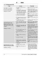
Page 34: ...edium is being drawn out of the separator 3 Too many weights in place or too much contact pressure 4 Excess wear on the screen or au ger 5 screen positioned incorrectly or clogged 6 auger channels clogged 7 screen only worn in certain places guide rails for the screen not set correctly 8 Slurry is pumped stirred too much ground fine 1 Inspect pump rotation direction and or control the pump capacit...

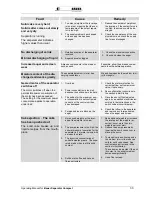
Page 35: ...d 2 Power consumption is too high because the solid cake is too hard 3 The setting for the maximum pow er consumption is not configured correctly or the control unit has been damaged 4 Foreign bodies are blocking the auger 1 Check the motor protection for correct setting set to maximum value if necessary 2 See configuration instructions in the section Initial Startup 3 Have the shut off limit adju...

Page 36: ...he supply medium is highly abrading 2 The blocking seal has been worn out by the duration of operation 1 Replace the pump with a low pressure pump 2 The blocking seal must be re placed before the second seal is damaged which would lead to damage to the bearing or the geared motor Problems that cannot be cor rected A problem as described above cannot be corrected despite optimal configuration accor...

Page 37: ...plain the individual electrical connections the cabling and the circuits Your electrician requires these circuit diagrams to connect the separator to the switch cabinet and your local power supply Every part and every component in the switch cabinet is numbered and listed in the parts list for the switch cabinet which is appended to the circuit diagrams in the switch cabinet Additional information...

Page 38: ...36 Operating Manual for Bauer Separator Compact S 16 NOTES ...

Page 39: ...ology methodology DIN EN ISO 12100 2 Safety of machinery Basic concepts general principles for design Part 2 Technical principles DIN EN 60204 1 Safety of machinery Electrical equipment of machines General requirements EN ISO 14121 1 Safety of machinery Risk assessment principles DIN EN 809 Pumps and pump units for liquids Common safety requirements The documents associated with the machine accord...

Reviews: