Operating Manual for
Bauer Separator Compact
15
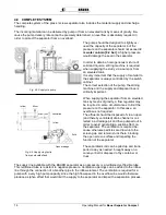
Abb 4.7 Standard-
Inflow
Overflow
The separator must be set up so that the solid can be freely
discharged. There must be a corresponding height difference
between the solid discharge point and the ground. The volume
of the cone of discharged material can be determined based on
the setup height.
The overflow line for the raw slurry as well as the drainage line
of the separated slurry should drain without pressure into the
corresponding storage tanks.
The overflow line should be run without a
“
siphon
”
in order to
avoid a lifting effect and to ensure good separator throughput
(see also section 14
“
Problems - Troubleshooting
”
.
Avoid winding, dipping and twisting of the pipeline and use tub-
ing that is resistant to negative pressure.
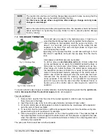
4.8.1 Inflow Setup
Screw the inflow element horizontally onto the inflow flange
(side of separator housing).
Connect the supply line to the lower horizontal connection
(socket DN100) of the inflow element. A tube of DN100 is re-
quired for this.
Connect the overflow line to the top horizontal outlet of the in-
flow element (socket DN100). A tube of DN100 is also required
for this.
A breather pipe or tube must be connected to the vertical con-
nection of the inflow element (socket DN100). This prevents the
buildup of negative pressure in the separator if the medium cre-
ates suction in the return line (siphon effect).
The breather tube should project at least 1.5 m above the over-
flow.
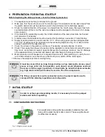
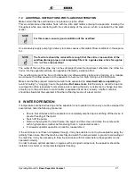
4.8.2 Drainage Line
Bolt the outlet bend for the separated slurry onto the outlet
flange (bottom of separator housing).
The drainage line is connected to this outlet bend. A tube of
DN100 is required for this.
Connection or transition elements for tubes (for the inflow and drainage lines) are available as acces-
sories from your dealer or the BAUER company.
NOTE
If no Bauer pump is installed, the pump for supplying the separator should have a pump rate
of at least 15 m³/h since the capacity of the separator otherwise cannot be fully utilized. To
keep pressure losses due to pipe friction low, the pipes should have a diameter of at least
100 mm (4").
NOTE
Inflow
V
e
n
til
a
tion
Overflow
Op
e
n
d
ra
ina
g
e
Open
ov
erf
low
Ventilation
Abb.4-7 Inflow Setup
Fig. 4-8 Drainage line

