2. DESCRIPTION
The MVD is a series of battery chargers that are based on a new “Hybrid” power
conversion system.
The two parts that are combined together to compose this “Hybrid” system are:
•
Special isolation transformer, with line frequency multiplication system;
•
High frequency switchmode converter, based on IGBT technology.
This system offers very high electrical efficiency, near unity power factor and very low
output current ripple, moreover it features a real universal charging capability: multi-
voltage, multi-current, multi-application.
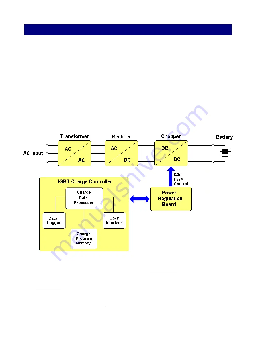
The electrical structure of the MVD charger is represented in the following block
diagram.
The TRANSFORMER reduces the AC input voltage and provides electrical insulation
between the input and the output of the charger. The RECTIFIER converts the AC output
of the transformer to an unregulated DC voltage.
The CHOPPER (operating at high frequency), regulates the output voltage and current to
the desired values. It generates a perfectly constant output current, with negligible ripple.
The IGBT CHARGE CONTROLLER is the main control unit of the MVD.
It's a microprocessor based electronic board, and it contains the USER INTERFACE
(Display, LEDs and Keyboard), the CHARGE PROGRAM MEMORY (where all the
programmed parameters are saved), the DATA LOGGER (where the charge history is
saved) and the CHARGE DATA PROCESSOR, which manages the entire charge
process.


