


page 71
page 71
page 71
page 71
page 71
160B&C TM
800-00140
NOTE:
NOTE:
NOTE:
NOTE:
NOTE: If the shaft bearings, shaft, valve block, or housing were not replaced, use the bearing spacer removed during the
disassembly procedure to preload the shaft bearings and perform step H. 13. If preload adjustment is
necessary, perform steps H.7. through H.13.
TA-19 SWING PUMP MAINTENANCE CONTINUED...
TA-19 SWING PUMP MAINTENANCE CONTINUED...
TA-19 SWING PUMP MAINTENANCE CONTINUED...
TA-19 SWING PUMP MAINTENANCE CONTINUED...
TA-19 SWING PUMP MAINTENANCE CONTINUED...
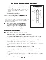
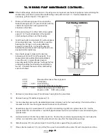
Front Bearing Installation
Front Bearing Installation
Front Bearing Installation
Front Bearing Installation
Front Bearing Installation
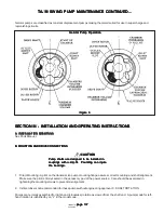
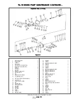
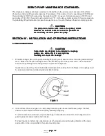
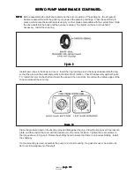
Figure 11
Figure 11
Figure 11
Figure 11
Figure 11
7.
Obtain a shaft bearing spacer kit and install the
thickest bearing spacer (13) over shaft (24) with the
chamfer facing into the housing (toward the
shoulder on the shaft).
8.
Slide new bearing (10) on the shaft and up against
spacer (13). The small diameter of the tapered
roller bearing must face out of the housing.
9.
Install housing (8) to valve block (51) without gasket
(9) and rotating group. Turn shaft (24) to seat the
bearings then torque to six housing attaching
screws (7) to five (5) lb. in. Check the opening
between the valve block and housing to be as even
as possible after tightening.
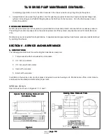
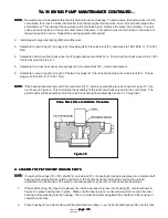
10.
Use a feeler gauge to measure the opening
between valve block (51) and housing (8). Four
measurements should be obtained equidistant
around the unit. A tapered feeler gauge is
especially useful for this purpose. Average the four
readings by adding them together and dividing by
four (4). Calculate thickness of the shaft bearing
spacer as follows:
+0.150
Measured thickness of bearing spacer
- 0.027
Average gap
+0.003
0.001
Preload setting
+0.020
Compressed thickness of gasket
0.146
0.001
Required bearing spacer to thickness
provide a 0.003 0.001 inch preload.
11.
Remove six mounting screws (7) and remove housing from the valve block.
12.
Remove bearing (10) and bearing spacer (13).
13.
Locate a bearing spacer with calculated dimensions and place next to the new bearing. Chamfer must face
shoulder on shaft. Use the original spacer if preload is not performed.
14.
Assemble spring (22), two washers (21) and (23), and retaining ring (20) into cylinder block (14). Set the
cylinder block S/A on a flat surface. Use Kraft paper between the block and surface to prevent scratching the
cylinder block.
15.
Install pin retainer (19) into the cylinder block (14). Position the pin retainer approximately 1/4 inch below the
surface, and orient the open end of the pin retainer to be away from the large spline openings.
16.
Slide three pins (18) into cylinder block S/A until they bottom against the pin washer (23).
17.
Place spherical washer (17) on top of the three pins; then install the shoe plate (16) with nine piston and shoe
+
-
+
-


