


page 68
page 68
page 68
page 68
page 68
160B&C TM
800-00140
TA-19 SWING PUMP MAINTENANCE CONTINUED...
TA-19 SWING PUMP MAINTENANCE CONTINUED...
TA-19 SWING PUMP MAINTENANCE CONTINUED...
TA-19 SWING PUMP MAINTENANCE CONTINUED...
TA-19 SWING PUMP MAINTENANCE CONTINUED...
10.
Inspect the bronze face of wafer plate (11) for excessive wear, scratches, and possible fracture. If the wafer
plate is fractured, make sure the new plate rests flat against the valve block at assembly and that wafer plate pin
(12) does not extend too far and hold the wafer plate away from the valve block.
11.
Inspect shaft (24) for broken splines, burrs, and wear in the area of shaft seal (40). Remove burrs with an India
stone. Wear in excess of 0.005 T.I.R. requires shaft replacement to prevent leakage.
12.
Inspect shaft bearing (38) for brinelling, pitting of the rollers and roughness when turned in race located in the
housing. If the bearing is defective, both the bearing and the race must be replaced. If the bearing race requires
removal, perform the following step.
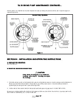
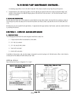
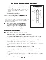
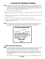
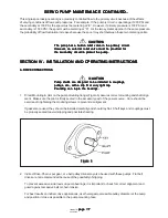
13.
Remove bearing race (38) from housing (8). Use special tool shown in Figure 5.
14.
Inspect housing (8) for cracks, cross threads and wear in the areas of pintle bearing races. Check each pintle
face for flatness and burrs. Check snap ring groove for wear and the proper depth. Check mounting face for
deep scratches that could cause leakage past the gasket. Clean up burrs and small scratches with an India
stone.
15.
Inspect pintle covers for flatness and burrs. Check the pintle seal for wear. Replace cover (26) if pintle seal is
defective.
16.
Check yoke bearings and bearing races for evidence of bearing seizure, brinelling, pitting of the rollers and
roughness when turned in the race. If a bearing is replaced, a yoke preload adjustment must be performed at
assembly.
17.
Inspect the valve block parts as follows:
a. Inspect the threaded plugs for worn corners on the hex head, stripped threads and burrs in the o-ring groove.
Use an India stone to remove burrs, if threads are defective replace plug.
b. Inspects springs (43) and (48) for damaged coils. Replace springs if coils are damaged. Inspect springs for
distortion. The ends of the springs must be parallel to each other. Replace springs if distorted.
c. Inspect the supercharge relief valve (49) for excessive wear, galling, erosion and burrs. The seat contact
area of the relief valve will have a bright circular contact area. Leakage paths across the relief valve will show
up as a break in the bright circular area. Erosion in the seat area may also cause a leakage path to
develop. Replace the valve if defective.
d. Inspect the two combination relief and check valves (45), or replenishing checks (44) if used. Refer to the
procedure developed in the previous step. If the valves are defective replace them with new assemblies.
e. Inspect valve block (51) for burrs, nicks, plugged body passages, flatness of the pump wafer plate area and
porosity. If a relief valve or a check valve is replaced, thoroughly inspect the valve block bore from which the
defective valve was removed. The valve seat may have eroded to a depth that a new valve cannot correct
cross check leakage. Repair or replace the valve block if defective.
G. ASSEMBLY OF VALVE BLOCK PARTS
G. ASSEMBLY OF VALVE BLOCK PARTS
G. ASSEMBLY OF VALVE BLOCK PARTS
G. ASSEMBLY OF VALVE BLOCK PARTS
G. ASSEMBLY OF VALVE BLOCK PARTS
NOTE:
NOTE:
NOTE:
NOTE:
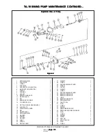
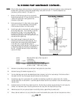
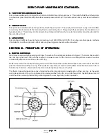
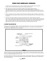
NOTE: Refer to Figure 8 during the following assembly procedure.
NOTE:
NOTE:
NOTE:
NOTE:
NOTE: Check the flatness of the valve block face in the areas around locating pins (50) and bolt openings. Use an India
stone to remove burrs or raised metal in these areas.
1. Install supercharge relief valve (49) into valve block (51). The valve must slide free within the bore and show no
evidence of bind when rotated through 360
o
.


