56-101-01175 Revision P Page | 71
APPENDIX C: DPS1000 INTERNAL PNEUMATIC DIAGRAM
Page 1: ...ight 2023 Barfield Inc All Rights Reserved DPS1000 RVSM Pitot Static Test Set USER INSTRUCTION MANUAL M N DPS1000 P N 101 01175 Doc P N 56 101 01175 Revision P March 9 2023 ___________________________...
Page 2: ...information contained herein is the sole property of Barfield Inc No intellectual property rights are granted by the delivery of this document or the disclosure of its content This entire document is...
Page 3: ...e CAUTION notice until required conditions are understood and fully complied with WARNINGS WARNING Do not use this equipment when it is not in its normal condition WARNING When testing with this equip...
Page 4: ...apable of damaging the aircraft instruments MARKING AND SYMBOLS This instrument meets the relevant European safety directives The instrument carries the CE mark Wi Fi disabled for EMC Units with MOD D...
Page 5: ...user of this equipment to be able to obtain the service covered by the warranty Visit the company website http barfieldinc com for publication updates Please send the Registration Card to BARFIELD IN...
Page 6: ...to obtain the list of approved repair facilities worldwide ensuring that this equipment will be serviced using proper procedures and certified instruments BARFIELD PRODUCT SUPPORT DIVISION Telephone 3...
Page 7: ...te I 260 01213 October 10 2017 TOC reformatted Operating limits modified Software Update procedure modified J 260 01217 May 11 2018 TOC reformatted Minor grammatical and formatting revisions Addition...
Page 8: ...able Key to Figure 11 Addition to Chapter 4 11 Aircraft Testing section Addition of Appendix E Wi Fi Connection Procedure M 260 01378 July 27 2022 Owner s Warranty Registration card updated Addition o...
Page 9: ...MATION 3 5 SOFTWARE UPDATE 3 6 TEST SET EQUIVALENT 4 CHAPTER 1 GENERAL 6 1 INTENDED USE 6 2 SPECIFICATIONS 6 3 INSTRUCTIONS FOR USE 13 4 TECHNICAL ASSISTANCE 13 CHAPTER 2 RATINGS 14 1 SUPPLY VOLTAGES...
Page 10: ...PREVENTATIVE 65 3 TROUBLESHOOTING 65 4 CALIBRATION 65 APPENDIX A ABBREVIATIONS GLOSSARY 66 APPENDIX B OPERATING LIMITS 68 APPENDIX C DPS1000 INTERNAL PNEUMATIC DIAGRAM 71 APPENDIX D MENU NAVIGATION 7...
Page 11: ...yed 26 Figure 23 Leak Measure Mode 27 Figure 24 Control Mode 28 Figure 25 Control Mode Select Hold 28 Figure 26 Hold Mode Select Resume 29 Figure 27 Target Value Keypad Screen 29 Figure 28 Display Set...
Page 12: ...78 Figure 69 Local UI Enable button 78 Figure 70 Remote Connected Remote UI disabled 79 Figure 71 Main Menu Screen Page 2 80 Figure 72 Numbered Keypad Screen 80 Figure 73 Setup 2 Screen 81 Figure 74 D...
Page 13: ...9 Table 6 Non MOD B Performance Accuracy 10 Table 7 Non MOD B Pressure Units Specifications 11 Table 8 Display Units 12 Table 9 Engine Pressure Ratio Test Table 61 Table 10 Aeronautical Limits Profil...
Page 14: ...ing the procedures and instructions detailed in this manual Do not use this equipment for any other purpose than that stated as the protection provided by the equipment may be impaired 2 INFORMATION P...
Page 15: ...Limited Two Year Warranty can be seen in Figure 3 3 RECERTIFICATION A The Test Set has a one year recertification requirement Maintenance required by this unit must be performed by qualified technicia...
Page 16: ...eet its designed accuracy specifications and especially so under varying operating temperature situations 4 MOBILE DEVICE S APP INFORMATION Visit the Apple App Store or Google Play App Store to downlo...
Page 17: ...50 and DPS500 Pitot Static Test Sets for all aircraft applications that fall within the range of 55 000 feet altitude 6 000 feet minute rate of climb and 650 knots airspeed Note The DPS500 is capable...
Page 18: ...arranty does not affect any other legal rights you may have by operation of law Contact BARFIELD at www Barfieldinc com or customer service at 305 894 5506 for warranty service procedures DISCLAIMER O...
Page 19: ...86 cm 14 8 in 37 6 cm 22 2 in 56 38 cm Weight 35 lbs 15 9 kg Table 1 Physical Characteristics B Environmental Environment Indoor or Outdoor use Operating Altitude 7 000 ft 2 134 m Operating Temp 0 C...
Page 20: ...t 20 ft 50 000 ft 22 ft 52 500 ft 27 ft 53 000 ft 2 of value 0 06 FS 4 1 3 kts 20 kts 0 5 kts 50 kts 0 3 kts 100 kts 0 2 kts 250 kts 0 2 kts 400 kts 0 2 kts 500 kts 0 2 kts 650 kts 2 of value Mach MAC...
Page 21: ...provides proof of accuracy and stability maintained over the recommended 12 month annual calibration cycle Unlike most 3rd party calibration services customer units calibrated and certified by Barfiel...
Page 22: ...3 Pt Channel Specification based on typical accuracy 0 06 FS As a result of the Qc Auto Zero the Qc Channel accuracy is 0 005 FS rising to 0 06 FS at Qc 25 6 inHg 650 kts Above 650 kts 25 6 inHg to 40...
Page 23: ...8 ft 50 000 ft 23 ft 55 000 ft 2 of value 0 06 FS 4 1 3 kts 20 kts 0 5 kts 50 kts 0 3 kts 100 kts 0 2 kts 250 kts 0 2 kts 400 kts 0 2 kts 500 kts 0 2 kts 650 kts 2 of value Mach MACH 0 15 and 1 0 0 00...
Page 24: ...e represents the DPS1000 internal leak rate with no hoses attached to the Static Ps or Pitot Pt If configured with AN4 ports the AN4 ports are capped PRESSURE UNITS NON MOD B Ps Channel Ps ROC Rate of...
Page 25: ...d kPa mmHg inH2O 4 C inH2O 20 C inH2O 60 F EPR inHg mbar psi mmHg kPa hPa inH2O 4 C inH2O 20 C inH2O 60 F Table 8 Display Units F Pressure Media Two internal high reliability electric pumps generate t...
Page 26: ...remote control device Barfield provides a custom App which is available as a free download from the Google Play Store and the Apple App Store The tablet mobile display will exactly mirror that of the...
Page 27: ...n ON OFF Switch and equipped with an internal fuse holder Figure 4 Power Entry Module B The Tester must be connected to the correct electrical power supply as stated beneath the power connector CAUTIO...
Page 28: ...25 ft Hose with quick disconnect and 1 tethered plug for Pitot Pt port connection P N 115 00629 3 Carrying Bag P N 195 00020 4 Instruction Manual P N 56 101 01175 this document 5 Power Cord 90 degree...
Page 29: ...either Android or IOS device 4 Wi Fi Application available as free download from either Google Play Store or Apple App Store Figure 6 Optional Travel Shipping Case Sized to qualify as a checked bag w...
Page 30: ...of the unit which must not be blocked Also there are intake vents on the left side for drawing air through the case which also must be kept free from obstructions Both sets of vents are labeled as sh...
Page 31: ...igure 10 DPS1000 Pressure Connections B Blanking Caps Used on OPT A only When not in use the panel mounted blanking caps should be fitted to the ports to prevent the introduction of any foreign matter...
Page 32: ...eferred to as the Pt Port and Total Pressure port 2 Static Ps Pressure Port Connect to Aircraft Static system This is also referred to as the Ps Port 3 Display Touch Screen Touch screen Graphic User I...
Page 33: ...d the need arise 3 ACCESSORIES A Included Items 1 Instruction Manual P N 56 101 01175 refer to Figure 13 2 Electrical Cable P N AE9887 ND refer to Figure 14 Key to Figure 12 Continued 5 Ground Earth S...
Page 34: ...00001 refer to Figure 16 5 Carrying Bag P N 195 00020 refer to Figure 17 6 AN4 Caps with Lanyard P N 176 00001 OPT A refer to Figure 18 Figure 13 Instruction Manual P N 56 101 01175 Figure 14 Electri...
Page 35: ...176 00001 OPT A B Items not included 1 Ruggedized shipping case Barfield P N 194 00073 refer to Figure 6 2 Nav Aids Pitot Static Adapters Contact Barfield with your aircraft requirements 3 Wi Fi enab...
Page 36: ...Test Set is completely calibrated and tested before shipment However to ensure the integrity of the tests the DPS1000 should be leak checked before each use To help automate this process use the pred...
Page 37: ...0 has two pneumatic control modes of operation 1 the default mode 2 channel Static and Pitot mode and 2 1 channel Pt Only mode which the user can select by following this Menu sequence Main Menu Page...
Page 38: ...Please refer to APPENDIX D MENU NAVIGATION for the complete menu navigation 7 TEST SET CONFIGURATION STATUS DISPLAY The Test Set presents the Configuration Status information in the top right quadrant...
Page 39: ...ate by either pressing the top right box or selecting this Menu sequence Main Menu Page 2 Setup 1 refer to Figure 22 Figure 22 Test Set Configuration Information Displayed Step 2 Select Setup 1 Step 3...
Page 40: ...he touch zones for those parameters are not active refer to Figure 23 6 While in Control mode the 4 parameters or 2 parameters displayed will have a Target value displayed when the Test Set transition...
Page 41: ...Refer to Figure 28 for an example of the ALT ROC CAS MACH display setup The user can enter the Target value for any of the 4 parameters by initially touching the parameter touch zone area which will...
Page 42: ...ressure at the Static Ps and Pitot Pt ports The displayed parameters ROC and RtCAS provide a relative but noisy instantaneous leak rate indication The touch screen is not active for any of the 4 or 2...
Page 43: ...ed areas Figure 28 Display Setup 4 Parameter Format Figure 29 Display Setup 2 Parameter Format C Units Displayed units Once the Display Setup has been selected Aeronautical Pressure units or EPR 4 par...
Page 44: ...gure 31 Display Units for Pressure Units Mode D Leak Testing There are two types of leak tests supported on the Test Set 1 the traditional leak testing using the Leak Rate Timer and 2 the Automatic Te...
Page 45: ...adiabatic instability b For Low Level Leak testing 5 000 ft a Wait Time of 1 00 min is recommended c For High Level leak testing 10 000 ft or high ROC a Wait Time of 5 00 minutes or more is recommende...
Page 46: ...s channel to ground prior to starting the Pt channel leak test d Wait The wait time is the time allowed for the system under test to settle and stabilize after the target CAS or ALT has been reached T...
Page 47: ...ected while operating in Leak Measure or Control mode refer to Figure 37 Note During Power ON initializations the Test Set measures ambient barometric pressure GROUND and stores it in a temporary memo...
Page 48: ...into the Qc transducer typically due to thermal component Test Set Warming or cooling The AutoZero function greatly improves the low airspeed 50 kts measurement accuracy Also the Test Set will remain...
Page 49: ...refer to Figure 39 Figure 39 Setup 1 1 Auto Leak Recovery When the Test Set is operating in Leak Measure mode and Auto Leak Recovery is Enabled If a high leak rate occurs High ROC or RtCAS then ALR w...
Page 50: ...56 101 01175 Revision P Page 37 Figure 40 Altitude Correction Screen Figure 41 Altitude Correction On Aircraft Figure 42 Altitude Correction Keypad...
Page 51: ...est Set Static Ps port is at ambient barometric pressure At the conclusion of the Go To Ground the Test Set will leave the Static Ps port vented to ambient while driving the Pitot Pt port to the Targe...
Page 52: ...following screen refer to Figure 45 will appear Figure 45 Setup 2 Selecting Limit File to Edit 1 Limits Create Edit Delete a Create Custom Limits Allows user to create custom limit profile s Note This...
Page 53: ...lows user to delete custom limit profile s refer to Figure 47 Note Before deleting a user created custom limit profile the user needs to ensure that it is not selected at the time of deletion The user...
Page 54: ...ion enables or disables the Wi Fi capability c Cabin Pressure Mode refer to APPENDIX F CABIN PRESSURE MODE Step 1 Touch Limits Create Edit Delete Step 2 Touch Delete Custom Limits Step 3 Ensure Limits...
Page 55: ...ote User must know the current PIN to change it J Touchscreen Calibration Main Menu Page 2 Page 3 Note If touch screen sensitivity or zone accuracy has shifted allow user to calibrate touch screen K L...
Page 56: ...at has occurred 5 An internal control channel leak test is performed The control channel leak test should not be confused with the actual leak test of the Test Set itself The control channels are very...
Page 57: ...values defined under the Limits menu Example with Limits default ALR for ROC 1 000 ft min and RtCAS 25 kts min the Test Set will automatically switch into Control mode with the Target values set to th...
Page 58: ...oller from the aircraft or instrument under test This is done to ensure that no transient pressure spikes are seen or impressed onto the UUT or aircraft while the internal control manifold is establis...
Page 59: ...d uses the Leak Rate Timer to measure the Leak Rate b Method 2 ATP Leak Test The Test Set has an automated feature called ATP Leak Test which allows the user to setup a profile ahead of time with the...
Page 60: ...lowing order a Pitot Pt channel Leak Test default 200 0 kts while Static Ps channel remains at ground ambient pressure If the Static Ps channel is not presently at ground the ATP will automatically pe...
Page 61: ...nu select Leak Testing and touch Leak Rate Timer e Review Wait Time and Leak Time refer to Figure 53 f To start the timer select Start Leak Test refer to Figure 53 The Wait timer starts counting down...
Page 62: ...ATP Leak Test Profiles c Follow the AMM or appropriate documents regarding the specific leak test required This information is necessary to create define the appropriate and safe ATP Leak Test profil...
Page 63: ...afe at Ground and vented before connecting the tester to the aircraft systems Note The ports on the Test Set and mating hoses are color coded to help prevent the accidental crossing of Static Ps and P...
Page 64: ...ments will begin moving towards this altitude at the VSI rate entered 9 Allow Test Set to stabilize at Target values for a minimum of 10 seconds before selecting Leak Measure mode 10 In Leak Measure m...
Page 65: ...itot System Leak Test and Static System Leak Tests have been completed Note It is always recommended that prior to performing any testing the Test Set and hoses should be leak tight The reality is eve...
Page 66: ...Leak Test Profiles The ATP Leak Profiles panel is displayed c Select the appropriate profile to perform the Leak Test as specified by the AMM or CMM d If required the default ATP profile can be select...
Page 67: ...ure the Test Set is powered ON Wait for Initialization to be completed the system to be safe at Ground and the display to indicate Vented Note If required select Go To Ground and wait for the Test Set...
Page 68: ...with aircraft instruments higher than Test Set the value would be entered as a positive number 10 At this time confirm the following have been accomplished a The Test Set and hose combination have be...
Page 69: ...te Test Set should be Vented to ambient and in Leak Measure mode at this time a From the Main Menu screen select the blue button page 2 b Select the Additional Functions button A screen is displayed w...
Page 70: ...zed procedure 13 Set the ALT Target value as specified by the AMM CMM or AP 14 Continue with the next ALT Target value required a For test procedures requiring small step changes in ALT there is a Nud...
Page 71: ...n touch the desired units 8 Ensure the limits selected are appropriate for the aircraft and or Instruments that are going to be tested 9 If there is a height difference between the Test Set and the ai...
Page 72: ...n CAS becomes the controlling parameter for the Pitot Pt channel Similarly if the user enters a MACH Target value then MACH becomes the controlling parameter With a Target value entered for MACH i e C...
Page 73: ...function and wait for the Unit Safe at Ground message to be displayed Note The above Nudge feature can be used with any of the Controlled Target parameters such as ALT ROC MACH RtCAS Ps Pt EPR 12 ENGI...
Page 74: ...increments of test 2 Method 2 EPR Testing using EPR Mode The Test Set has an actual EPR Mode that can be used to test the EPR transmitter EPR Pt Ps where Ps Inlet pressure and Pt Outlet pressure In EP...
Page 75: ...dures to return the Test Set and aircraft to ambient pressures 13 SHUTDOWN PROCEDURE A Test Set Shutdown Procedure 1 From the Main Menu select the Go to Ground function 2 Confirm the Go to Ground by s...
Page 76: ...101 01175 Revision P Page 63 4 Switch power OFF 5 Disconnect the Static Ps and Pitot Pt hoses from the aircraft ports and or adapters 6 Disconnect the Static Ps and Pitot Pt hoses from the tester por...
Page 77: ...factory shipping container and packing materials be retained should it become necessary to re ship the Test Set for a variety of reasons including O E M recertification B Ensure the Test Set is Safe a...
Page 78: ...ROUBLESHOOTING A If the unit displays an error code during use please record the error code and contact Barfield or its representative for further instructions before proceeding B If the Test Set seem...
Page 79: ...ted Air Speed kts or km h CMM Component Maintenance Manual EPR Engine Pressure Ratio o F Degrees Fahrenheit o C Degrees Celsius ft Foot g Gauge hr Hour hm Hecto meter inHg inches of Mercury HUIM Host...
Page 80: ...Pt pressure change Qc Differential pressure Qc Pt Ps QFE Local atmospheric pressure QNH Barometric pressure at sea level ROC Rate Of Climb in units of ft min or m min Rt Rate RtCAS Rate of change of C...
Page 81: ...tom limits profile the Test Set will power up using the last profile selected The following tables represent the default and max limits profile values included in the Test Set AERONATICAL LIMITS PROFI...
Page 82: ...Enabled default ALR ROC 2 000 ft min 600 m min ALR RtCAS 200 kts min 370 km h min Table 11 Aeronautical Limits Profile max PRESSURE LIMITS PROFILE DEFAULT Parameters Limits Comments Ps Min 2 693 inHg...
Page 83: ...ssure Ps Max 32 000 inHg Ps Maximum Pressure Pt Min 2 693 inHg Pt Minimum Pressure Pt Max 62 000 inHg Pt Maximum Pressure EPR Min 0 10 EPR Minimum EPR Max 12 0 Ps Maximum Rate RtEPR Min 0 50 inHg min...
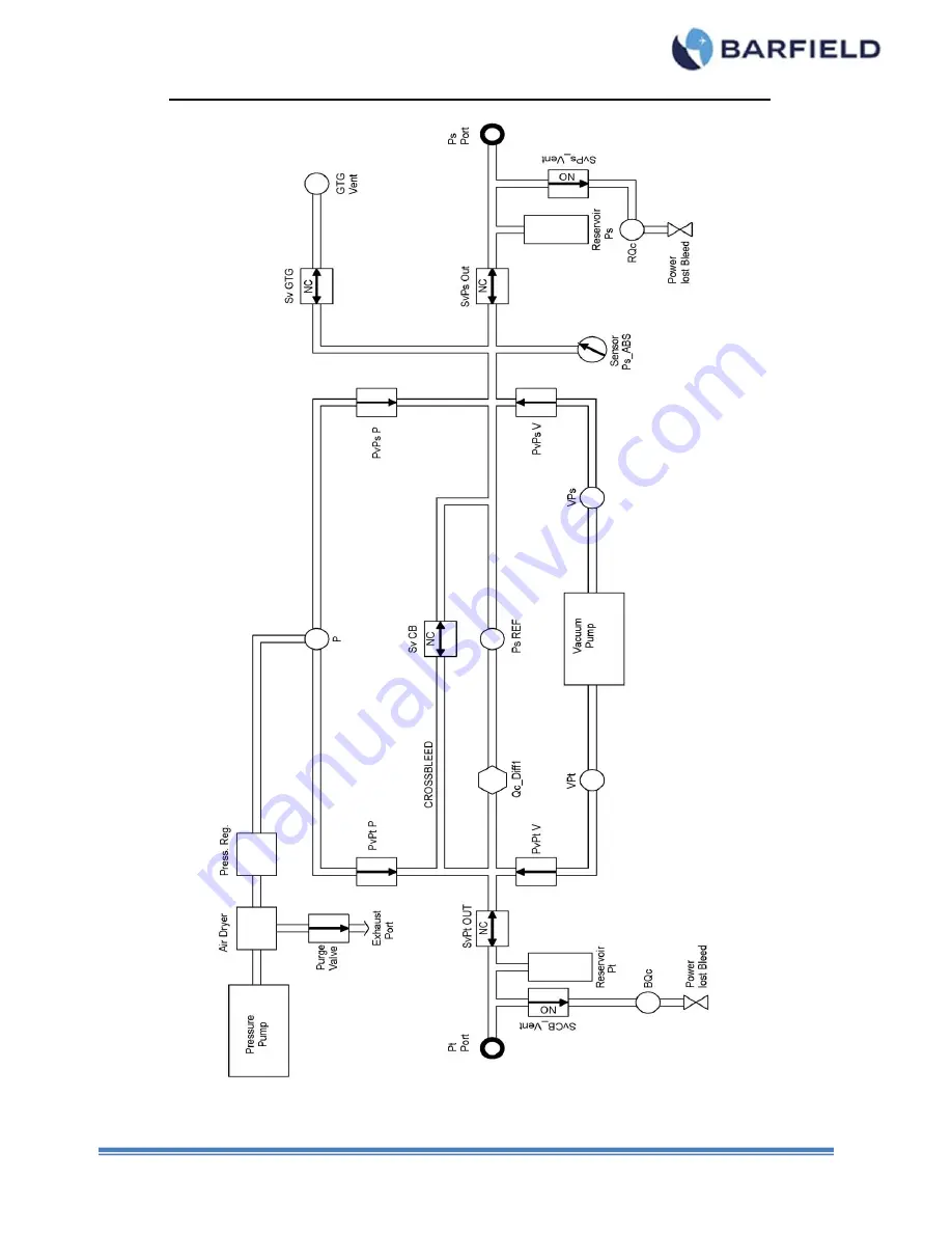
Page 84: ...56 101 01175 Revision P Page 71 APPENDIX C DPS1000 INTERNAL PNEUMATIC DIAGRAM...
Page 85: ...56 101 01175 Revision P Page 69 APPENDIX D MENU NAVIGATION...
Page 86: ...DTS Note Refer to doc no 42 101 01175_01178 for additional information on the firmware update procedure for the DPS1000 1811NG units 1 ESTABLISHING WI FI CONNECTION FOR ANDROID DEVICES A Establishing...
Page 87: ...ed to your Android device s Wi Fi connection Settings screen 7 Connect to available DPS1000 1811NG Wi Fi 8 If connecting to your android device for the first time a password request will trigger refer...
Page 88: ...app is now ready for use with the Test Set 2 ESTABLISHING WI FI CONNECTION FOR iOS DEVICES A Establishing Wi Fi Connection 1 Launch the Barfield ADTS app from your device 2 Press Connect refer to Fig...
Page 89: ...i 7 Connect to available DPS1000 1811NG Wi Fi connection refer to Figure 65 Figure 65 DPS1000 1811NG Wi Fi Selected 8 If you are connecting your iOS device to the DPS1000 1811NG Wi Fi for the first ti...
Page 90: ...rfield ADTS app is now ready for use with the Test Set 3 DISCONNECTION WI FI CONNECTION FOR ANDROID iOS DEVICES A Disconnecting from Wi Fi Connection 1 Properly disconnect the Android or iOS device fr...
Page 91: ...e and Local UI enable buttons are enabled 1 To enable the DPS1000 s touchscreen press the Local UI enable on the Test Set refer to Figure 69 The touchscreen is now enabled despite the remote being con...
Page 92: ...56 101 01175 Revision P Page 79 3 A yellow button on the remote s screen will indicate Remote Connected Remote UI disabled refer to Figure 70 Figure 70 Remote Connected Remote UI disabled...
Page 93: ...e Test Set as shipped from Barfield Section A below describes the process of enabling the Cabin Pressure function while Section B describes the actual usage of the Cabin Pressure Mode 1 CABIN PRESSURE...
Page 94: ...Setup 2 screen is displayed refer to Figure 73 Select System Configuration Figure 73 Setup 2 Screen 5 A screen appears with three options Select Cabin Pressure Mode Disabled refer to Figure 74 Figure...
Page 95: ...ressure Mode To access the mode restart the Test Set B Using Cabin Pressure Mode 1 Turn the Test Set ON 2 Allow the initialization to complete 3 The Test Set will then prompt you to answer Yes or No t...
Page 96: ...1 of the Cabin Pressure Mode ensure that the cabin of the aircraft is open and the Pitot Pt port of the unit is vented to ambient Static Ps port connection not required Refer to Figure 78 for an exam...
Page 97: ...warning pop up window is displayed with the message below refer to Figure 79 Select Yes Figure 79 Warning Screen 1 9 Step 2 window is displayed refer to Figure 80 Here the unit will vent to ambient F...
Page 98: ...Pressure Note Ensure that the cabin is sealed and ready for pressurization as per AMM Figure 81 Cabin Pressure Mode Step 3 7 Upon pressing the Cabin Measure button the Test Set will vent to ambient 8...
Page 99: ...rization procedure and the unit will display the measured pressures and rates Note As a safety feature the following conditions will be monitor and a visual warning will be issue by the unit If a rate...
Page 100: ...rocess refer to Figure 85 Figure 85 Venting Process 14 Once the venting process is completed the Test Set will display the message below refer to Figure 86 Set the power switch to OFF Figure 86 Unit S...
Page 101: ...vere environmental conditions 1 IBF SYSTEM MODE A Accessing IBF system mode 1 Set power switch to ON 2 Allow the initialization to complete 3 Connect the standard Static Ps channel hose to the Test Se...
Page 102: ...ons 7 A new screen will appear with 4 options refer to Figure 89 Select IBF Inlet Barrier Filter Mode Figure 89 Select IBF Inlet Barrier Filter Mode 8 Step 1 window is displayed with the message below...
Page 103: ...re 91 Figure 91 Warning Message 1 10 Step 2 window is briefly displayed while the Test Set is venting to ambient and performing Tear function refer to Figure 92 Figure 92 IBF Mode Step 2 Note The Test...
Page 104: ...ue both ALT dP set to the current pressure measure on the Static Ps port 13 Select ALT or dP 14 A keypad screen is displayed refer to Figure 94 Enter Target values Then press Enter Note Initially the...
Page 105: ...p up message will appear Select Yes refer to Figure 95 Figure 95 Warning Message 2 19 The Test Set will briefly vent and a new window is displayed with the message below refer to Figure 96 Press Ok Fi...
Page 106: ...56 101 01175 Revision P Page 93 APPENDIX H FIELD FIRMWARE UPDATE PROCEDURE VIA USB BARFIELD ADTS APP Refer to the 42 101 01175_01178 for this procedure...