


8 6
C H A N GE PARA METERS
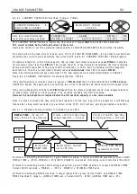
6.5.1.1 B
l
ock d
i
agram of contactor contro
l
ST ART/J O G
A
l
arms are
reset by a
h
i
gh to
l
o w
trans
i
t
i
on
T 3 2 J O G
T 3 3 S T ART
T 3 1 RUN
HIG H = O N
LO W = O FF
0 V S WIT C H
The contactor
contro
l
re
l
ay has
a 2 4 V co
il
w
i
th a
1 0 0mS hardw are
off de
l
ay. The
co
il
i
s on
l
y
energ
i
sed w
i
th
C ST OP at 2 4 V
A ND the 0 V
s w
i
tch on (HIG H)
Dr
i
ve run
PIN
1 6 7
A NDED
J O G
PIN 3 0 6
A NDED
ST ART
PIN 3 0 7
A NDED
RUN
PIN 3 0 5
INTERN AL
RUN
PIN 3 0 8
T 3 4 C S T OP
T 3 5 + 2 4 V
A
l
o w RUN
i
nput sets
drop out de
l
ay to zero
Drop out de
l
ay IP
Enab
l
e
From
zero
i
nter
l
ock
H
i
gh for Supp
l
y
synchron
i
sat
i
on
H
i
dden PIN 7 2 0
System reset
pu
l
se
ALARMS A
ll
Hea
l
thy w hen
h
i
gh
PIN 6 9 8
2 second
off de
l
ay
Dr
i
ve start
PIN
1 6 6
J O G
f
l
ag
PIN
6 8 9
RE A D Y
f
l
ag
PIN
6 9 9
T 4 7
L A T 1
T 4 8
L A T 2
T 4 5
C O N 1
T 4 6
C O N 2
C O N T A C T OR C O N TROL
ST OP M O DE RA MP
PIN 1 3 1
Speed
Feedback
Rect
PIN 5 8
L
i
ve de
l
ay
mode
PIN 6 0
Drop out
De
l
ay
PIN 5 7
Stop t
i
me
li
m
i
t
PIN 5 9
Drop out
Speed
C ontactor drop
Out
TIMER
C ontro
l
l
og
i
c
C ontactor
C ontro
l
Enab
l
e
C ontro
l
l
og
i
c
Interna
l
enab
l
e
Stop mode
Ramp t
i
me.
To speed
contro
l
b
l
ock
Stop mode
Ramp t
i
me
PIN 5 6
Tota
l
speed
Ref + ref pr
i
or
to the Run
Mode Ramp
ZERO
Inter
l
ock
PIN 1 1 7
Zero
i
nter
l
ocks
Speed
l
eve
l
PIN 1 2 3
Tota
l
Speed
Reference
PIN 1 2 0
Zero speed
f
l
ag
Rect
PIN 1 3 1
Speed
Feedback
PIN 1 1 9
Zero ref f
l
ag
Rect
Rect
Rect
PIN 1 1 6
Zero ref
Start enab
l
e
Zero ref start
contro
l
l
og
i
c
To current
contro
l
l
og
i
c
PIN 1 1 8
ZI current
l
eve
l
PIN 1 2 1 A t
S’st
ill
f
l
ag
To f
i
r
i
ng ccts
PIN 1 1 5
Standst
ill
enab
l
e
PIN 1 2 2
Zero speed
l
ock
Standst
ill
and
pos
i
t
i
on
l
ock
contro
l
l
og
i
c
Summary of Contents for PLX
Page 2: ...2 Contents ...
Page 202: ......